Background
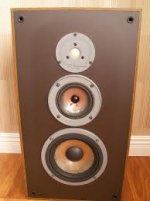
This build started as a rebuild of my Infinity 3 Way bookshelf model RS8B speakers. I bought them in the early 80’s and when the surrounds went I made the mistake of replacing the drivers instead of re-foaming. When I measured them about a year ago I discovered how bad the response was. I spent a lot of time trying to model them with the replacement drivers I had used with no luck. Additionally all the drivers are not flush mounted making for some ugly diffractions. I realized that to salvage them I would have to replace the baffle and crossover. At this point I decided to just start over and planned to use the Audax HM170Z0 woofers in a new box and crossover.
This build started as a rebuild of my Infinity 3 Way bookshelf model RS8B speakers. I bought them in the early 80’s and when the surrounds went I made the mistake of replacing the drivers instead of re-foaming. When I measured them about a year ago I discovered how bad the response was. I spent a lot of time trying to model them with the replacement drivers I had used with no luck. Additionally all the drivers are not flush mounted making for some ugly diffractions. I realized that to salvage them I would have to replace the baffle and crossover. At this point I decided to just start over and planned to use the Audax HM170Z0 woofers in a new box and crossover.
Attachments
Initial design
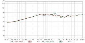
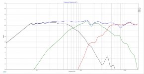
Before I started ordering parts, Madison Sound put the SB Acoustics SB23CACS45-4 8" ceramic woofer on sale for $89.00 each. Having just used the 5 inch version in my towers as a mid-range and liking the sound I figured why not go bigger than the 6.5 inch Audax woofers so I bought them. I already had a pair of Fountek NeoCd1.0 1.5 Ribbon Tweeters so all I needed was a pair of mid-range drivers. Finally I choose to use the just released SB12MNRX2-25-4 mid-range. While waiting for these to cross the ocean in a slow boat I build my test enclosure. I decided to try a trapezoidal enclosure even if it was going to be more difficult to build. I had been reading about all the benefits of non-parallel sides on internal reflections. After waiting 3 months for the mid-ranges I finally ran some measurements of the very stylish test enclosure. Much to my surprise and that of others on this forum a trapezoidal enclosure makes an ugly mess of edge diffractions. I was disappointed but I decided that an old school rectangular baffle would sound sound better than my mid-century modern cabinet. The green graph is the trapezoidal baffle and the red is a rectangular baffle.
Before I started ordering parts, Madison Sound put the SB Acoustics SB23CACS45-4 8" ceramic woofer on sale for $89.00 each. Having just used the 5 inch version in my towers as a mid-range and liking the sound I figured why not go bigger than the 6.5 inch Audax woofers so I bought them. I already had a pair of Fountek NeoCd1.0 1.5 Ribbon Tweeters so all I needed was a pair of mid-range drivers. Finally I choose to use the just released SB12MNRX2-25-4 mid-range. While waiting for these to cross the ocean in a slow boat I build my test enclosure. I decided to try a trapezoidal enclosure even if it was going to be more difficult to build. I had been reading about all the benefits of non-parallel sides on internal reflections. After waiting 3 months for the mid-ranges I finally ran some measurements of the very stylish test enclosure. Much to my surprise and that of others on this forum a trapezoidal enclosure makes an ugly mess of edge diffractions. I was disappointed but I decided that an old school rectangular baffle would sound sound better than my mid-century modern cabinet. The green graph is the trapezoidal baffle and the red is a rectangular baffle.
Attachments
Final design
The Enclosure
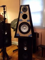
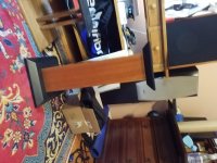
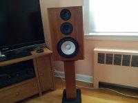
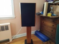
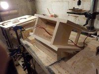
So after a year of designing I end up with something very conventional, a rectangular box with the external dimensions of 21” x 13.5” x 12.75”. I decided to go sealed because I intend to use them in my office to listen to 2 channel music and the original RS8B’s were sealed. I went back and forth with driver placement but finally vertically aligned them instead of offsetting the mid-range or tweeter. This might have been a mistake but what I have read either alignment will have its advantages. The internal volume nets about 32 liters and a Qts of .732 after accounting for the drivers, 2.5 liter mid-range chamber and woofer displacement. I braced the cabinet with two horizontal braces that connect the sides and front and backs. These braces also create the top and bottom of the mid-range enclosure. I ripped some scrap MDF at 45 degrees and glued to the back of the mid-range chamber to breakup any reflections, I don’t know if it matters, but it didn’t cost anything. Everything is made of ¾ inch Baltic birch, except the baffle and the back panel. The baffle is ¾ inch MDF and ½ MDF laminated together and the back is just ¾ MDF. This is not the big box MDF, it is not brown, but the whiter stuff, not even close in quality and unfortunately not close in price. Finally I veneered it in striped mahogany fished with 3 coats of amber shellac. It has grills made of 1/8 inch hardboard attached by magnets buried under the veneer. I had leftover BB and veneer so I copy a picture of some stands I saw on the internet, clear a patent infringement.
The Enclosure
So after a year of designing I end up with something very conventional, a rectangular box with the external dimensions of 21” x 13.5” x 12.75”. I decided to go sealed because I intend to use them in my office to listen to 2 channel music and the original RS8B’s were sealed. I went back and forth with driver placement but finally vertically aligned them instead of offsetting the mid-range or tweeter. This might have been a mistake but what I have read either alignment will have its advantages. The internal volume nets about 32 liters and a Qts of .732 after accounting for the drivers, 2.5 liter mid-range chamber and woofer displacement. I braced the cabinet with two horizontal braces that connect the sides and front and backs. These braces also create the top and bottom of the mid-range enclosure. I ripped some scrap MDF at 45 degrees and glued to the back of the mid-range chamber to breakup any reflections, I don’t know if it matters, but it didn’t cost anything. Everything is made of ¾ inch Baltic birch, except the baffle and the back panel. The baffle is ¾ inch MDF and ½ MDF laminated together and the back is just ¾ MDF. This is not the big box MDF, it is not brown, but the whiter stuff, not even close in quality and unfortunately not close in price. Finally I veneered it in striped mahogany fished with 3 coats of amber shellac. It has grills made of 1/8 inch hardboard attached by magnets buried under the veneer. I had leftover BB and veneer so I copy a picture of some stands I saw on the internet, clear a patent infringement.
Attachments
The Crossover
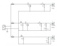
I picked 500Hz and 4KHz for crossover points. This is my second three way and I found the textbooks are correct and the band-pass need to be at least 3 octaves or more. Anything smaller and the low pass and high pass elements will create some really strange responses. I used my 3 channel amplifier built around the Dayton Audio DSPB-100 to verify these crossover points. I then used XSim and ran through at least 12 iterations before settling on my final design. I was able to simplify it quite a bit, but still ended up with Zobels and two L-Pads. I was able to remove the baffle step compensation circuits on both the mid-range and woofer. I assume this is mostly because of the crossover point which is very near the baffle step frequency. After removing the BSC from the simulation I adjusted the component values to smooth what little baffle step that remained. I use L-Pads instead of series resisters because L-Pads seem not change the transfer function of the filter as much. Lastly I adjusted the L-Pad values by measuring and listening to music after using XSim to give starting points.
I picked 500Hz and 4KHz for crossover points. This is my second three way and I found the textbooks are correct and the band-pass need to be at least 3 octaves or more. Anything smaller and the low pass and high pass elements will create some really strange responses. I used my 3 channel amplifier built around the Dayton Audio DSPB-100 to verify these crossover points. I then used XSim and ran through at least 12 iterations before settling on my final design. I was able to simplify it quite a bit, but still ended up with Zobels and two L-Pads. I was able to remove the baffle step compensation circuits on both the mid-range and woofer. I assume this is mostly because of the crossover point which is very near the baffle step frequency. After removing the BSC from the simulation I adjusted the component values to smooth what little baffle step that remained. I use L-Pads instead of series resisters because L-Pads seem not change the transfer function of the filter as much. Lastly I adjusted the L-Pad values by measuring and listening to music after using XSim to give starting points.
Attachments

The measurements
My biggest challenge is getting clean measurements, I don’t have a suitable space indoors and I live on a busy corner which makes outdoor measurements a challenge. Mostly I measure indoors and do my best to ignore room effects. When I made my outdoor measurements I put the DUT on top of a 6 foot ladder and test at 95db level because of the street noise. These are the measurements used for my final simulation and my completed system FRD. Overall I’m satisfied with the results, there is a wiggle between 1KHz and 2KHz. I have no doubt this is an edge diffraction on the mid-range and I if I had mounted the driver closer to one edge it might have gone away.
My biggest challenge is getting clean measurements, I don’t have a suitable space indoors and I live on a busy corner which makes outdoor measurements a challenge. Mostly I measure indoors and do my best to ignore room effects. When I made my outdoor measurements I put the DUT on top of a 6 foot ladder and test at 95db level because of the street noise. These are the measurements used for my final simulation and my completed system FRD. Overall I’m satisfied with the results, there is a wiggle between 1KHz and 2KHz. I have no doubt this is an edge diffraction on the mid-range and I if I had mounted the driver closer to one edge it might have gone away.
Attachments
Conclusions
They measure decently, look great and sound quite good. I’m happy with the bass even without a sub-woofer, I was concerned because they are sealed. They don’t sound as good as my towers but they cost 60% less and they are in my office which is not a good room.
They measure decently, look great and sound quite good. I’m happy with the bass even without a sub-woofer, I was concerned because they are sealed. They don’t sound as good as my towers but they cost 60% less and they are in my office which is not a good room.
Just a comment. Most ribbon tweeters require at least a 3 pole filter, better if 4. I have played with it before and discovered it to be true especially if your cut off frequency is so low. Might have okay if it was 10kHz or so. The reason is ribbons have very poor excursion, so you have to keep the mids away from it.
My two cents.
Oon
My two cents.
Oon
Nicely done. The end result measures well, and it looks good!
I agree. Getting good measurements is one of the more challenging aspects.
Another thing: I like the way your documented your project. Your posts above are very well written.
My biggest challenge is getting clean measurements, I don’t have a suitable space indoors and I live on a busy corner which makes outdoor measurements a challenge.
I agree. Getting good measurements is one of the more challenging aspects.
Another thing: I like the way your documented your project. Your posts above are very well written.
Just a comment. Most ribbon tweeters require at least a 3 pole filter, better if 4. I have played with it before and discovered it to be true especially if your cut off frequency is so low. Might have okay if it was 10kHz or so. The reason is ribbons have very poor excursion, so you have to keep the mids away from it.
My two cents.
Oon
Interesting, I actually started with a 3rd order on the Mid to Tweeter when I was testing using a DSP three amplifier and the LR2 measured and sounded better. If I redo the XO in the future I will try a 3rd oder again. Not sure how I could cross at 10Khz with a three way, crossing at 4Khz is as far as I wanted to push the mid. I have two ways with this same tweeter based on Scott Selin's Rhodium design that sounded good and even using a 4 inch mid woofer I could never imagine crossing that high.
Nicely done. The end result measures well, and it looks good!
I agree. Getting good measurements is one of the more challenging aspects.
Another thing: I like the way your documented your project. Your posts above are very well written.
Thanks, I spent a lot of time typing it up in MS Word, then I mapped out which photos to attach to each post, maybe I should have been a technological😀 writer instead of a technician.
😀
Nice work!
On your graph, the 1.4khz ripple peak corresponds to a 4.8in distance from edge to driver center. Judging from the photo, that looks like the symmetric side to center distance of the mid range driver. On your rectangular baffle, I wonder if that distance is simply wider and hence the ripple gets pushed to a lower frequency where it has less effect due to the crossover filter? I think the trapezoid near the tweeter is more important and if near the mid, consideration to make sure equal distances still don’t occur in your frequency of interest. That’s why offset placement on a rectangle works so well. So maybe a wider trapezoid would be better than rectangular of same width at the frequency of interest? This implies that the trapezoid will be bigger than the rectangle, to get the same performance for a midrange.
Much to my surprise and that of others on this forum a trapezoidal enclosure makes an ugly mess of edge diffractions.
On your graph, the 1.4khz ripple peak corresponds to a 4.8in distance from edge to driver center. Judging from the photo, that looks like the symmetric side to center distance of the mid range driver. On your rectangular baffle, I wonder if that distance is simply wider and hence the ripple gets pushed to a lower frequency where it has less effect due to the crossover filter? I think the trapezoid near the tweeter is more important and if near the mid, consideration to make sure equal distances still don’t occur in your frequency of interest. That’s why offset placement on a rectangle works so well. So maybe a wider trapezoid would be better than rectangular of same width at the frequency of interest? This implies that the trapezoid will be bigger than the rectangle, to get the same performance for a midrange.
Your front baffle looks to be about 12" x 20" with the mid centered about 13" from the bottom. Below is what the baffle diffraction looks like.
Your mid and tweeter also look to be badly out of phase at about 8kHz where you see the effects of a cancelation in the summed response. If you can't do anything to align the phase better, the response might be improved if you center a little tanking capacitor on the mid at that frequency. Place it in parallel with L3 if that's not ringing any bells. Maybe a resistor in series with the capacitor could be warranted as well. Simming it will let you know.
Your mid and tweeter also look to be badly out of phase at about 8kHz where you see the effects of a cancelation in the summed response. If you can't do anything to align the phase better, the response might be improved if you center a little tanking capacitor on the mid at that frequency. Place it in parallel with L3 if that's not ringing any bells. Maybe a resistor in series with the capacitor could be warranted as well. Simming it will let you know.
Attachments

...Overall I’m satisfied with the results, there is a wiggle between 1KHz and 2KHz. I have no doubt this is an edge diffraction on the mid-range and I if I had mounted the driver closer to one edge it might have gone away.
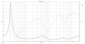
That wiggle is also in the IEC baffle in SB measurements. As it is also accompanied by a little jump in the impedance trace, I would guess that unfortunately it is a treat of the driver...
//
Wow, it has been a while since there has been any traffic in the thread, thanks to all. Interestingly enough I'm in the process of evaluating active cross overs and might convert this to active. I won't be changing the baffle, but maybe I can make a better XO and EQ some of the bigger problems.
Thanks for the great theory explaining why the trapezoid didn't measure well. I don't think a bigger trapezoid would work for me, it was suggested that 35 degree angles instead of 11.25 degree angles I used might be the solution, but this makes a very large and ugly box.
Very close, the baffle is 21 by 13.5 and the mid is centered at 13.25. Thanks for the suggestions, if I stay passive I will try some of these ideas. If I do go active I should be able to fix the 8Khz problem and maybe a few others.
Yes, I noticed this after I posted. Do you think EQ could help at all? The wiggle even shows on a free are measurement.
Nice work!
On your graph, the 1.4khz ripple peak corresponds to a 4.8in distance from edge to driver center. Judging from the photo, that looks like the symmetric side to center distance of the mid range driver. On your rectangular baffle, I wonder if that distance is simply wider and hence the ripple gets pushed to a lower frequency where it has less effect due to the crossover filter? I think the trapezoid near the tweeter is more important and if near the mid, consideration to make sure equal distances still don’t occur in your frequency of interest. That’s why offset placement on a rectangle works so well. So maybe a wider trapezoid would be better than rectangular of same width at the frequency of interest? This implies that the trapezoid will be bigger than the rectangle, to get the same performance for a midrange.
Thanks for the great theory explaining why the trapezoid didn't measure well. I don't think a bigger trapezoid would work for me, it was suggested that 35 degree angles instead of 11.25 degree angles I used might be the solution, but this makes a very large and ugly box.
Your front baffle looks to be about 12" x 20" with the mid centered about 13" from the bottom. Below is what the baffle diffraction looks like.
Your mid and tweeter also look to be badly out of phase at about 8kHz where you see the effects of a cancelation in the summed response. If you can't do anything to align the phase better, the response might be improved if you center a little tanking capacitor on the mid at that frequency. Place it in parallel with L3 if that's not ringing any bells. Maybe a resistor in series with the capacitor could be warranted as well. Simming it will let you know.
Very close, the baffle is 21 by 13.5 and the mid is centered at 13.25. Thanks for the suggestions, if I stay passive I will try some of these ideas. If I do go active I should be able to fix the 8Khz problem and maybe a few others.
That wiggle is also in the IEC baffle in SB measurements. As it is also accompanied by a little jump in the impedance trace, I would guess that unfortunately it is a treat of the driver...
//
Yes, I noticed this after I posted. Do you think EQ could help at all? The wiggle even shows on a free are measurement.
- Home
- Loudspeakers
- Multi-Way
- My lock down project - SB and Fountek 3 way bookshelf