Hi guys, I need some help in designing a crossover for this line array speaker, we bought 8pcs of these speakers from Alibaba, and it turned out they do know how to copy drivers but the crossover was a joke. Ok all together for someone who doesnt know nothing about audio it probably would be okay, but not for us.
So the setup is:
2*10 inch (4ohm each)
B&C Speakers
1*8 inch(16ohm)
B&C Speakers
2*3inch hf drivers (8ohm each)
B&C Speakers
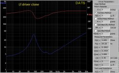
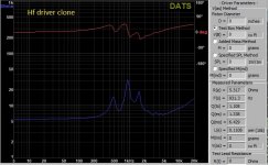
Keep in mind our speakers are not the original bc speakers these are quite good clones as you will be able to see from the impedance measurements.
Also it is a speculation, I am by no means sure that these would be in the orginal v8s. Based on coil size throat size, and the looks of the drivers we were able to sort of identify them.
We had a friend come over to measure the drivers with dats V3, unfortunately he really had no ideea how to use the dats and I certainly never used it so these measurements could be a little off. I think at the time he shorted the terminals of the dats to compensate for its resistance but i am not sure about other fine tuneing procedures we should have done before measurements. These were my first ever impedance measurements of any sort
So based on the impedance curve, the 10 inch and the 8 icnh drivers are at least similar to the bc speakers ones but the hf drivers impedance curve has an extra peak compared to the impedance curve found on the bcspeakers website.
My original problem is that i know these speakers could sound a lot lot better, but my problem is that pretty much over 10khz the hf drivers wont really sound, i disconnected the passive crossover network and used my xilica DSP(at the time i did not have the impedance measurements yet) to try and make a crossover based on Mr. AllenB s passive xover tutorial.
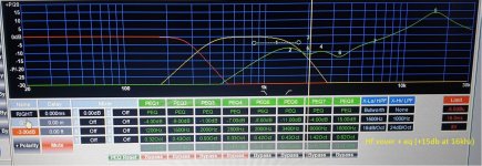
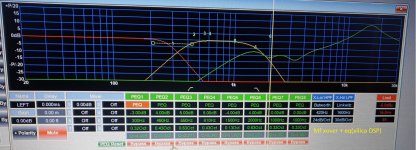
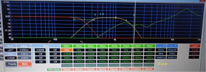
The conclusion was that i have got to a point where the speaker really had a clean crystal clear tone which was appealing to my ears it really did sound AMAZING. I will upload the pic of the xilica xover i made. The real problem afterall is that i needed to add an eq of +9dB pretty much over 7khz to get the drivers to sound good. When making this crossover on the xilica I had Smaart to wiev the phase and the magnitude of the speaker. I think i used ECM8000 mic for these tests. In the effort of making the response of the speaker as close to flat as possible also keeping the drivers in their optimal operating range.
After this i thought of making that exact same xover i made on the xilica but making it a passive xover, sadly i soon realised higher order filters wont really work for me bacause of many factors(first problem is size, after that comes price and power handling,etc). I soon realised this is not gonna work.
My next approach was to design a filter that wont cost a fortune, that will handle power (afterall we have been pushing these speakers around 2-3kw at the end of the day) and will make the drivers operate at optimal conditions, reusing as many parts off the original passive network as possible. My final choice became 2nd order bw for the 10s, and 3rd order for the bandpass drivers upper cutoff, as well as the hf drivers(to eliminate all the peaks and dips i had measured with smaart.
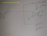
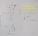
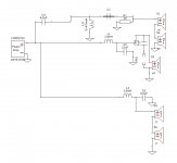
At this moment i quickly drew a schematic off the xover that came with the drivers and my judgement told me it was horrible, so i decided i wont simply play with the existing xover (since clearly it was a 2 way xover and it was made in to a 3way xover later on) but i will let decide everyone about this circuit(pic uploaded). In the original setup the speakers had their 10s in series for a total impedance of 8 ohms, the mid is 16 ohm, and the hf driveres were put in paralell for a total impedance of 4 ohms.
So after countless hours of reading i designed the actual xover with impedance flattening and all, and based on the impedance measurements and the graphs of the bc speakers i came to a conclusion that the ideal frequencies to cross at would be 500hz and 2100hz(i used a simple 2 way xover calculator but tried to estimate impedances as best as i could, calculating in the hf drivers impedance flattening resistor, wireing the two 10s in series for 8ohm, also the hf driveres are in series to achieve 16ohm, the midrange driver is 16ohm aswell) but when making the actual prototype i realised i needed a lot of help with the inductors.
There are a couple of values i cannot really achieve without a laminated or other type of core, but i do not know how to make sure i do not get around the saturation point of the core. I mean i have an lcr and i have a laminated core, i could get down and make my inductor with magnat wire, but then again how do i know what gauge of wire to use to handle these currents. Ballparking it isnt gonna cut it for me because i cant afford to disassemble these speakers every day to see if it works, could anyone point me in the right direction please? What is the procedure for sizing the GA of the inductors magnatwire?
In the meantime i did a quick google search to see if there are any other xovers readily available for the V8 since a lot of companies copy these speakers in china with minor differences between eachother, i can sort of imagine some dudes copying the cabinet, other dudes copying the speakers and other dudes copying xovers etc other stuff, and finally another dude buys the pieces and pieces it together. At the end of the day the company that sells these speakers actually has no clue what they do to the point they couldnt show a graph off the speakers output when we asked. Not a single graph, nothing.
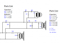
After some googling i have found an xover that is claimingly being made for the v8, and it has the crossover frequencies of 450hz/2100hz
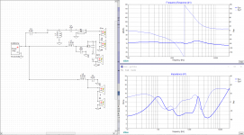
so i took the time and reverse engineered it based on the pics i have found at the sellers page(not knowing the values of the components), but i was curious to see the order of the filters etc. to compare it to my circuit. Keep in mind i did not draw the ptc in this scematic diagram.
So the big question is should i go first and second order or should i go second and third order? Also how do i take in consideration the power handling of the speakers when designing the xover? I found out with the capacitors i can calculate their max voltage easily but with inductors?
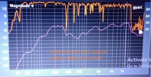
I also uploaded a pic in smaart showing the graph of the speaker phase and magnitude, with the crossover it came with, there are no eqs nothing applied it is just fed with pink noise.
Thank you for reading my mess and thank you all for your replies!
So the setup is:
2*10 inch (4ohm each)
B&C Speakers
1*8 inch(16ohm)
B&C Speakers
2*3inch hf drivers (8ohm each)
B&C Speakers
Keep in mind our speakers are not the original bc speakers these are quite good clones as you will be able to see from the impedance measurements.
Also it is a speculation, I am by no means sure that these would be in the orginal v8s. Based on coil size throat size, and the looks of the drivers we were able to sort of identify them.
We had a friend come over to measure the drivers with dats V3, unfortunately he really had no ideea how to use the dats and I certainly never used it so these measurements could be a little off. I think at the time he shorted the terminals of the dats to compensate for its resistance but i am not sure about other fine tuneing procedures we should have done before measurements. These were my first ever impedance measurements of any sort
So based on the impedance curve, the 10 inch and the 8 icnh drivers are at least similar to the bc speakers ones but the hf drivers impedance curve has an extra peak compared to the impedance curve found on the bcspeakers website.
My original problem is that i know these speakers could sound a lot lot better, but my problem is that pretty much over 10khz the hf drivers wont really sound, i disconnected the passive crossover network and used my xilica DSP(at the time i did not have the impedance measurements yet) to try and make a crossover based on Mr. AllenB s passive xover tutorial.
The conclusion was that i have got to a point where the speaker really had a clean crystal clear tone which was appealing to my ears it really did sound AMAZING. I will upload the pic of the xilica xover i made. The real problem afterall is that i needed to add an eq of +9dB pretty much over 7khz to get the drivers to sound good. When making this crossover on the xilica I had Smaart to wiev the phase and the magnitude of the speaker. I think i used ECM8000 mic for these tests. In the effort of making the response of the speaker as close to flat as possible also keeping the drivers in their optimal operating range.
After this i thought of making that exact same xover i made on the xilica but making it a passive xover, sadly i soon realised higher order filters wont really work for me bacause of many factors(first problem is size, after that comes price and power handling,etc). I soon realised this is not gonna work.
My next approach was to design a filter that wont cost a fortune, that will handle power (afterall we have been pushing these speakers around 2-3kw at the end of the day) and will make the drivers operate at optimal conditions, reusing as many parts off the original passive network as possible. My final choice became 2nd order bw for the 10s, and 3rd order for the bandpass drivers upper cutoff, as well as the hf drivers(to eliminate all the peaks and dips i had measured with smaart.
At this moment i quickly drew a schematic off the xover that came with the drivers and my judgement told me it was horrible, so i decided i wont simply play with the existing xover (since clearly it was a 2 way xover and it was made in to a 3way xover later on) but i will let decide everyone about this circuit(pic uploaded). In the original setup the speakers had their 10s in series for a total impedance of 8 ohms, the mid is 16 ohm, and the hf driveres were put in paralell for a total impedance of 4 ohms.
So after countless hours of reading i designed the actual xover with impedance flattening and all, and based on the impedance measurements and the graphs of the bc speakers i came to a conclusion that the ideal frequencies to cross at would be 500hz and 2100hz(i used a simple 2 way xover calculator but tried to estimate impedances as best as i could, calculating in the hf drivers impedance flattening resistor, wireing the two 10s in series for 8ohm, also the hf driveres are in series to achieve 16ohm, the midrange driver is 16ohm aswell) but when making the actual prototype i realised i needed a lot of help with the inductors.
There are a couple of values i cannot really achieve without a laminated or other type of core, but i do not know how to make sure i do not get around the saturation point of the core. I mean i have an lcr and i have a laminated core, i could get down and make my inductor with magnat wire, but then again how do i know what gauge of wire to use to handle these currents. Ballparking it isnt gonna cut it for me because i cant afford to disassemble these speakers every day to see if it works, could anyone point me in the right direction please? What is the procedure for sizing the GA of the inductors magnatwire?
In the meantime i did a quick google search to see if there are any other xovers readily available for the V8 since a lot of companies copy these speakers in china with minor differences between eachother, i can sort of imagine some dudes copying the cabinet, other dudes copying the speakers and other dudes copying xovers etc other stuff, and finally another dude buys the pieces and pieces it together. At the end of the day the company that sells these speakers actually has no clue what they do to the point they couldnt show a graph off the speakers output when we asked. Not a single graph, nothing.
After some googling i have found an xover that is claimingly being made for the v8, and it has the crossover frequencies of 450hz/2100hz
so i took the time and reverse engineered it based on the pics i have found at the sellers page(not knowing the values of the components), but i was curious to see the order of the filters etc. to compare it to my circuit. Keep in mind i did not draw the ptc in this scematic diagram.
So the big question is should i go first and second order or should i go second and third order? Also how do i take in consideration the power handling of the speakers when designing the xover? I found out with the capacitors i can calculate their max voltage easily but with inductors?
I also uploaded a pic in smaart showing the graph of the speaker phase and magnitude, with the crossover it came with, there are no eqs nothing applied it is just fed with pink noise.
Thank you for reading my mess and thank you all for your replies!
Attachments
-
 lf.jpg108.6 KB · Views: 566
 -
 v8xoversoros.png21.8 KB · Views: 661
 -
 clonexo.jpg190.7 KB · Views: 278
 -
 origxo.jpg86.6 KB · Views: 307
 -
 hfxo.jpg355 KB · Views: 223
 -
 mfxo.jpg456.7 KB · Views: 464
 -
 lfxo.jpg468.1 KB · Views: 447
 -
 hf.jpg106.3 KB · Views: 460
 -
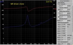 mf.jpg109.6 KB · Views: 471
 -
 origmeres2.jpg196.1 KB · Views: 303
Last edited:
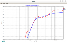
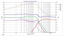
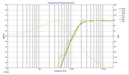
This graph would be the 18db/oct filter applied to the measured hf driver? I am sorry this is the first time i try to design an xover.. I now downloaded xsim and will try to use it too. Based on this graph with this xover i wouldnt need an equaliser over 10khz, if i udnerstand the graph right? I might be totally off, in that case again, i am sorry.
Thank you for your time and help!
Thank you for your time and help!
I was showing that the bumpy impedance causes a bumpy response.
A compression driver crossover is usually a little harder to do than a dome tweeter. The crossover you show has a 40 ohm resistor to reduce the impedance variations. This is not enough. If you want to change this you should use an RLC circuit, or maybe more than one, to deal with the impedance.
A compression driver crossover is usually a little harder to do than a dome tweeter. The crossover you show has a 40 ohm resistor to reduce the impedance variations. This is not enough. If you want to change this you should use an RLC circuit, or maybe more than one, to deal with the impedance.
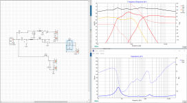
Okay so, i realised i made a few mistakes in the drawing of the original xover. I redid it all in xsim, and i delayed the mf and hf drivers in such a manner where i got closest whit the frequency response to the measured frequency response and tried to mimic the phase to some extent. Here is the end result of the original speaker. Its a joke isnt it? look at that medium frequency crossover... FAIL i think.
I am going to try and fix up this current xover to see how it does and ill try the hf drivers in series aswell.
I am going to try and fix up this current xover to see how it does and ill try the hf drivers in series aswell.
Attachments
I don't know, there are some discrepancies..
You appear to be using a flat response for the midrange it has natural rollofs that would be important to see in this sim, and which affect phase.
Are S1 and S4 the same? S3 and S5? Do you have 2 capacitors in series for the tweeter?
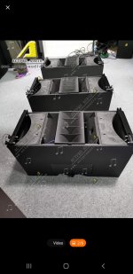
If we can clear up which drivers have what information you can share the *.dxo file here.. Can you answer this, why are there two tweeters? It may make a difference.
You appear to be using a flat response for the midrange it has natural rollofs that would be important to see in this sim, and which affect phase.
Are S1 and S4 the same? S3 and S5? Do you have 2 capacitors in series for the tweeter?
If we can clear up which drivers have what information you can share the *.dxo file here.. Can you answer this, why are there two tweeters? It may make a difference.
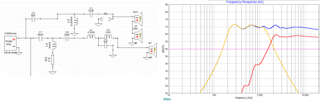
Yes, s1 and s4 respectively s3 s5 aswell are exactly the same, there are two hf drivers just because in the original line array speaker they have the same configuration. I have uploaded an image of the chinese clones so you can atleast have an image in your head how they look. Now i have been playing around with the xsim software, and i can make pretty flat figures, but my question here is, how much of a variation is acceptable on the impedance graph? Later on i will try to measure the phase for the FRD file. I am quite sure i have equipment i can do this with just not sure which software to use. I have uploaded a corrected version of the earlier xover, it is nowhere near finished product, i still need to add a filter to create the bandpass effect on the mids. Would this impedance curve be acceptable? Or i should try to make it even flatter?
Thank you kind sir!
Thank you kind sir!
Attachments
Also here is the dxo files. I made a couple of variants earlier just to see how the software works, and also out of curiosity. Here are the dxo files attached. That circuit with the two caps in series, was the original crossover network that came installed in these speakers(post nr 5). And we used these speakers with this trash in them...
How exactly would one flatten the compression drivers impedance?
How exactly would one flatten the compression drivers impedance?
Attachments
Last edited:
This is going to require some assumptions at first. Some simplifications to get started with.configuration. I have uploaded an image
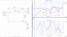
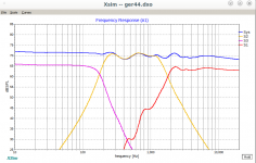
I've cleaned it up a bit. I installed the impedance files in the right places, set them for derived impedance phase and reset the driver levels and offsets. I haven't changed the crossover.xsim software,
Firstly, you have no response data and are looking only at the filter responses. Do you have FRD files that I didn't see?
Holmimpulse, REW and ARTA could do it.I am quite sure i have equipment i can do this with just not sure which software to use.
Yes.i still need to add a filter to create the bandpass effect on the mids.
Putting the inductor back in the tweeter circuit has helped a lot. Later, you might consider the crossover frequencies and levels. These won't be too easy so I'll just post what I have at the moment.Would this impedance curve be acceptable? Or i should try to make it even flatter?
Attachments

Sadly i did not measure frd ever. Could you point me to some kind of tutorial? Thank you for the help! I am going to try and refine the xover even further. I still need about 3-4days to measure frd because i am not in town right now I will post any further info and the frd files asap. Thank you a thousand times!
I will post any further info and the frd files asap. Thank you a thousand times!Okay so i have been working on the crossover, my problem was with the 275hz fs of the mid driver, it wouldnt want to let me make a good crossover for it, simply it was too bumpy and the values were unreal(of the crossover). So i added a series notch filter because i thaught that is the easy way to go, well it did not work as expected but i did make it work. I am certainly not sure about the lf drivers cutoff tho, i might try third order, i feel like there could be a lot of phase problems easy, with this setup. I also checked power dissipation of R4 which should be all good. My inductors seem a little high but i think thats down to the drivers. Would this crossover be acceptable? Please make any changes you feel would help in my project sir!
Thank you for all your time! You help a LOT!
Thank you for all your time! You help a LOT!
Attachments
We are just playing now. Learning Xsim. Later you will use response files, measure driver levels, consider directivity..Would this crossover be acceptable?
To start you can use a target file to try and match your response, like I've done here with the tweeter.
Attachments
It is difficult when you don't have *.frd files. The natural rolloff is not there, you have to push harder with the filters.my problem was with the 275hz fs of the mid driver, it wouldnt want to let me make a good crossover for it,
Attachments
Hmm okay, but to my understanding i should be away from the fs of the drivers with an octave or so, if i see it right, wouldnt this mean that the middrivers highpass filter should be arond 500hz if the fs is 275? Also i see that there are a lot of huge value parts, so i am guessing this xover is a theoretical example or so, until i get the frd measurements, am i right? Thnak you!
I also noticed every driver was inverted, that was on purpose i think, wasnt it? I see the phase curve of this xover is a lot different than what my design did, this is how the phase should look like(your design)? I am sorry for all these beginner questions, it is a lot to understand when designing filters..
Yes firstly this is just an example and I wanted to have a frequency spread. But, the choice of crossover frequency depends on a number of things. These appear to be horn loaded. If they can keep up with the lower frequency it would depend on other things.should be arond 500hz if the fs is 275?
It makes the plots easier to see. If I don't do that the phase flips from top to bottom at the crossover frequency.I also noticed every driver was inverted, that was on purpose i think, wasnt it?
This is not a good example, it is rough and unrealistic. However, which (of the four phase plots) are you talking about?I see the phase curve of this xover is a lot different than what my design did, this is how the phase should look like(your design)?
I was wondering about the system phase i referred to, my problem is that i am quite sure the bad hf response of this system is due to some kind of phase problems. Even when i had the digital sound processor and i have measured the delays for each driver, set them as the software calculated and even after that i still ahd to add a massive eq at 10khz, like 15db or so, you can see this on the earlier picture i attached with the xilica dsp. Although i did not try to invert the polarity of the hf drivers etc i am thinking since i have connected eahc set of speakers to a channel of amplifier and applied a digital crossover and i have got the same, pretty much hf just disappeared over 9-10khz, unless i added that eq of 15db. Though i did not try reversing the polarity of the hf drivers. I attached a picture of a measurement in smaart, which shows the system phase as orange and the frequency response in pink. Tomorrow i will go and try measuring the frd files. I have a focusrite soundcard and a behringer ecm8000, is this going to be enough for frd measurements? Thank you, sorry for the noob questions again!
Attachments

- Status
- This old topic is closed. If you want to reopen this topic, contact a moderator using the "Report Post" button.
- Home
- Loudspeakers
- Multi-Way
- D&B V8 line array clone high power passive crossover design