I recently finished my first DIY-loudspeaker project. I want to tweak it a little and have a question about the crossover design.
If I change the woofer inductor from 1,5 mh to 1,8 mh, how will this change the sound and will it have any significant effect on the sound?
If I change the woofer capacitor from 8,5uf to 7uf, how will this change the sound and will it have any significant effect on the sound?
The background for these questions is that I find the sound a bit to hard in the upper mid range and I'm thinking of installing a notch filter as in the design below, but even without the notch filter the design is slight different to the one I have (therefore my two questions). The notch filter itself seem to be two resistors (5,6ohm instead of 5ohm and an additional 1,5 ohm) as seen in the design below:
Also, I don't want to spend a fortune in high quality filter components without doing proper measurements of my speaker since I've read that it is needed when using the Scanspeak woofers due to construction differences in each unit.
Anyway, except from som wise replies on my two questions, any suggestion on further reading to find answers on my questions are much appreciated. I want to learn how to calculate this myself in the future.
Many thanks!
An externally hosted image should be here but it was not working when we last tested it.
If I change the woofer inductor from 1,5 mh to 1,8 mh, how will this change the sound and will it have any significant effect on the sound?
If I change the woofer capacitor from 8,5uf to 7uf, how will this change the sound and will it have any significant effect on the sound?
The background for these questions is that I find the sound a bit to hard in the upper mid range and I'm thinking of installing a notch filter as in the design below, but even without the notch filter the design is slight different to the one I have (therefore my two questions). The notch filter itself seem to be two resistors (5,6ohm instead of 5ohm and an additional 1,5 ohm) as seen in the design below:
An externally hosted image should be here but it was not working when we last tested it.
Also, I don't want to spend a fortune in high quality filter components without doing proper measurements of my speaker since I've read that it is needed when using the Scanspeak woofers due to construction differences in each unit.
Anyway, except from som wise replies on my two questions, any suggestion on further reading to find answers on my questions are much appreciated. I want to learn how to calculate this myself in the future.
Many thanks!
I suspect you'll find the issue is more a case that in the 2.5 Clones, the Scan woofer and tweeter are being expected to work higher and lower (respectively) than either can really manage optimally. From your description, you've run into precisely the same issue that many builders did.
Upping the primary to 1.8mH will damp output a bit (and alter the phase alignment without changes elsewhere, although how good that is anyway in the 2.5 Clone I don't know off the top of my head). Yes, you'll likely hear it. Probably not dramatic, but audible. In effect you'll have a lower filter Q, especially if you back off the value on the shunt cap (i.e. a slightly more damped corner frequency) and even more if you add the resistor in series with the shunt cap. It might help.
To be honest, I'd probably be inclined to leave it alone, and put the money toward a different tweeter that can get a bit lower with grace. Troels ended up with the Scan 9500 for e.g. Thing about the 2.5 Clones is (AFAIK) it was never absolutely clear whether ProAc's drivers were modified relative to the stock units.
Last edited:
Troels also aimed to make the clones sound neutral, not keeping the original Proac sound:
http://www2.audiokit.it/ITAENG/Altoparlanti/ScanSpeak/The%202.5%20clone%20paper.pdf
Page 43.
I'm not routing for making my speakers sound neutral. However, I just want them to sound less "hard", "loud" or with "less resonance" in the upper mid frequency. What you suggest is the most easy and less expensive solution for this. Adding the resistor in the woofer? Will this lower the upper mid frequency a bit?
I would like to try them with a tube amplifier also. Do you think the sound of a tube amplifier will be less "squealing"?")
The Response 2.5 800 Hz bump, by the way, could
be the explanation for the acceptance of the 2 kHz
bump in the original design.
The “sum” of these two bumps may kind of even out
the overall perceived balance.
(Actually we can now get both of these bumps with
the new coated drivers from SS. Leave out (or
reduce) the series resistor in the LP section, and leave
out the LCR notch filter for removing the 800 Hz
bump + reduce tweeter series resistor to 5 ohm!
How about that? Finally we can recreate the original
ProAc Response 2.5 sound/profile with all the
bumps).
In the history of HIFI, response curves displaying
excessive bass and treble at the expense of a recessed
midrange, was the trademark of the so called “West
Coast” sound. Lots of bass and lots of treble.
Excellent for “Surfin’ USA” by The Beach Boys.
I remember JBL having a 14” bass driver (LE14)
married to a small paper cone tweeter. This was a
“tizz and boom” speaker!
If you have to make a living of producing
loudspeakers, you have to catch the attention of your
audience, and the easiest way to do this, is pushing
the “loudness” button = “west-coast-sound”.
http://www2.audiokit.it/ITAENG/Altoparlanti/ScanSpeak/The%202.5%20clone%20paper.pdf
Page 43.
I'm not routing for making my speakers sound neutral. However, I just want them to sound less "hard", "loud" or with "less resonance" in the upper mid frequency. What you suggest is the most easy and less expensive solution for this. Adding the resistor in the woofer? Will this lower the upper mid frequency a bit?
I would like to try them with a tube amplifier also. Do you think the sound of a tube amplifier will be less "squealing"?
I remember this Proac 2.5 clone project by Troels. It's a tricky woofer. He struggled with it as he often has with scan 18W woofers. He has said quite often it's not an ideal woofer for a two-way. It's just the nature of the beast that paper cones can sound hard. They break up much harsher than polycones.
It looks like Version 3 of Troels' modified crossover is the one to go for. With some slightly modified values and the new 2kHz LCR notch. But version 2 can't be all that worse, and much easier.
Notice your two initial schematics are inaccurate. The 47R goes AFTER the 4.7uF.
Worth a try if you are seriously invested in these speakers. It's actually quite a high 3.2kHz third order tweeter filter, so the tweeter ought to be comfortable. You could try a 15R/0.33uF Zobel if it's a bit bright at the top.
I don't think 20% changes to components make much difference, TBH. It's only 10% in all usually, being a square root relationship. Room placement has bigger effects.
Last edited:
I remember this Proac 2.5 clone project by Troels. It's a tricky woofer. He struggled with it as he often has with scan 18W woofers. He has said quite often it's not an ideal woofer for a two-way. It's just the nature of the beast that paper cones can sound hard. They break up much harsher than polycones.
Sometimes; not all the time. Depends on the paper pulp (and precise plastic composition), the cone geometry, what decoupling &c. are applied. I can think of a few plastic cones that have exceedingly unpleasent resonances.
Notice your two initial schematics are inaccurate. The 47R goes AFTER the 4.7uF.
Notice those schematics are in fact accurate depictions for the filter
Attachments
Last edited:
Troels also aimed to make the clones sound neutral, not keeping the original Proac sound:
Which would be fine if that's what you had. Except you don't. Not exactly: ProAc's drivers were modified. Not massively AFAIK, but enough.
I'm not routing for making my speakers sound neutral. However, I just want them to sound less "hard", "loud" or with "less resonance" in the upper mid frequency.
Which is what I said: you've run into the problem many 2.5 Clone builders have run into, which is caused by trying to run a midbass driver higher than it's happy going, and a tweeter lower than it's happy going. They don't really meet in the middle. Not without excess resonance / 'hardness' through cone modes + HD (midbass) and HD (tweeter), plus the shift in polars.
What you suggest is the most easy and less expensive solution for this. Adding the resistor in the woofer? Will this lower the upper mid frequency a bit?
A little, but it's unlikely to solve the fundamental issue, just reduce it a bit.
I would like to try them with a tube amplifier also. Do you think the sound of a tube amplifier will be less "squealing"?
Valve amplifiers vary as much as solid state; they are not all created equal in terms of their electrical behaviour so there is no consistent / 'one size fits all' answer to that one. This is a moderately reactive load though, so PP is probably necessary to be able to swing the necessary current.
A problematic speaker IMO. I have heard that scruffy looking 18W/8535 crossed at 2kHz, and it's a very good driver then,
Here, there are no easy solutions.
There is a hope in that LCR notch IMO, and I might try the Version 2 in Troels' PDF, though you sound confused what the rest of the stuff does.
Third order filters are part of the repertoire:

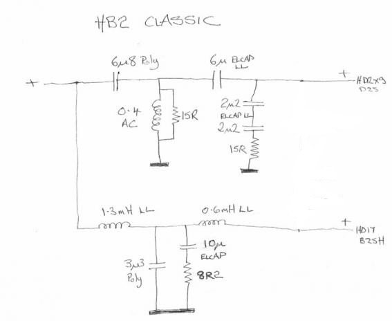
Seen one, you've seen them all? The Heybrook HB2:
A better way to do this might be as a 3 way:
SP38/13
For comparison, another 2nd order style with Scan 18W and a lower 2.5kHz crossover point:
Studio-101
Interestingly, Troels doesn't rate the Scan D2010/8513 when digging low. He mentions this in the SP38 build. So another option might be a better tweeter. Quite a rebuild job though.
Here, there are no easy solutions.
There is a hope in that LCR notch IMO, and I might try the Version 2 in Troels' PDF, though you sound confused what the rest of the stuff does.
Third order filters are part of the repertoire:
Seen one, you've seen them all? The Heybrook HB2:
A better way to do this might be as a 3 way:
SP38/13
For comparison, another 2nd order style with Scan 18W and a lower 2.5kHz crossover point:
Studio-101
Interestingly, Troels doesn't rate the Scan D2010/8513 when digging low. He mentions this in the SP38 build. So another option might be a better tweeter. Quite a rebuild job though.
The background for these questions is that I find the sound a bit to hard in the upper mid range and I'm thinking of installing a notch filter as in the design below, but even without the notch filter the design is slight different to the one I have (therefore my two questions). The notch filter itself seem to be two resistors (5,6ohm instead of 5ohm and an additional 1,5 ohm) as seen in the design below:
This isn't a notch filter. The 1.5Ω resistor is to alter the woofer roll off to give a better phase response. It is not optional!
This isn't a notch filter. The 1.5Ω resistor is to alter the woofer roll off to give a better phase response. It is not optional!
It seems to be true, because Troels omitted the notch filter (see version 6 of the filter) with this resistor. It wasn’t needed anymore. Anyway, I will re-design the filter with new resistors according to Troels design in version 6, but keep my inductors. Then I’ll wait until I have proper measurement equipment.
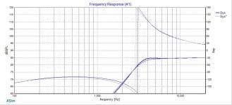
For example, the attached. Flat 8ohm load & FR from 0Hz - 20KHz for clarity / illustration. Grey = high pass filter values as depicted. Blue = same high pass filter values with the resistor moved downstream of the 4.7uF cap.
Many thanks for this illustration. I interpret this as if I would like the sound to be a bit more dimmed in the 3-4KHz it is a good idea to move the resistor and place it after the capacitor? Am I correct?
If so, I will try 👍
To be honest, I'd probably be inclined to leave it alone, and put the money toward a different tweeter that can get a bit lower with grace. Troels ended up with the Scan 9500 for e.g. Thing about the 2.5 Clones is (AFAIK) it was never absolutely clear whether ProAc's drivers were modified relative to the stock units.
Well, you are probably right about the new tweeters. But then I need to buy new tweeters with new and increased recessed speaker holes. I will not do that for these speakers. For the next project I would lile to try one of Troels 3-way speakers 😁
I would also like to try to try a digital crossover, such a miniDSP with 8 or 12-channel DAC and amplifier. But that is another topic!
Many thanks for this illustration. I interpret this as if I would like the sound to be a bit more dimmed in the 3-4KHz it is a good idea to move the resistor and place it after the capacitor? Am I correct?
No, the reverse, you already have that. I was simply using it to show my [our] friend Steve (System7) that the circuit diagrams you posted are actually correct representations of the circuit and how the resistor position it affects the electrical damping. If you moved it downstream of the second cap from where it is at the moment, you would have an underdamped response, i.e. the opposite of what you're trying to do.
One cheap thing you can try (and easily reversible) if you want a bit more damping in that region: replace the 47ohm shunt resistor with a 33ohm. That will damp it down a little. Not saying you will find it an improvement, but it's not exactly expensive to try.
Last edited:
Well, you are probably right about the new tweeters. But then I need to buy new tweeters with new and increased recessed speaker holes. I will not do that for these speakers. For the next project I would lile to try one of Troels 3-way speakers 😁
Fair enough. The Scan [Discovery] and Seas ones are rather nice.
I would also like to try to try a digital crossover, such a miniDSP with 8 or 12-channel DAC and amplifier. But that is another topic!
Slippery slope, this audio...
I remember reading this 6" plus 3/4" Troels Gravesen Proac 2.5 Clone design project a long time back:http://www2.audiokit.it/ITAENG/Altoparlanti/ScanSpeak/The%202.5%20clone%20paper.pdf
Phew, what a nightmare. All 43 pages of fiddling about!
Why do you bother?
Still, if you have these drivers and cabinet, I guess you, at least, might do your best with it.
So it seems Troels decided the damped third order filter in version 6 does the right things.
Starting from here:
As I think you do, the V6 seems to be simple and nearly as good as it gets. It's well established that adding resistance to the shunt capacitor damps the bass rolloff curve. I wouldn't sweat too much about the smaller 1.5mH coil, just increase the capacitor proportionally. The 0.83mH coil can be reduced to 0.47mH by unwinding about 1/4 of the turns.
He still has misgivings about the 98mm soft-dome 3/4" Scan D2010/8513 tweeter. My own experience is soft domes only work well on 4th. order filters. Stops them shrieking, and in this case, going to sibilance. Clearly a 1" soft dome is going to be easier even at 3kHz XO, and he tries the Scan D2905/9500 albeit with some fiddling to remove the ferrofluid.
A 98mm tweeter is awkward to replace without some cabinet work and level adjust. Maybe the metal SEAS 22TAF/G is worth trying even if not a genuine 104mm 1" tweeter, but by all accounts it's quite good on simple filters:
H1283-06 22TAF/G
I was going to attach some images, but my current Linux OS is struggling. As long as we all have read all 43 pages of Troels, we are on the same page here.
Last edited:
Starting from here:
An externally hosted image should be here but it was not working when we last tested it.
As I think you do, the V6 seems to be simple and nearly as good as it gets. It's well established that adding resistance to the shunt capacitor damps the bass rolloff curve. I wouldn't sweat too much about the smaller 1.5mH coil, just increase the capacitor proportionally. The 0.83mH coil can be reduced to 0.47mH by unwinding about 1/4 of the turns.
Many thanks. I will post an image of the filters with schematics when I’m done. And of course with some listening experience words too. Perhaps then a second round of tweaking. I will leave the crossovers outside the cabinet until I’m good! 😁😁😁
Hi FredJJ,
It seems you currently are using the original Chinese crossover of the ProAc Response 2.5. However, there are two issues with that.
More information is available here: DIY ProAc Response 2.5
It seems you currently are using the original Chinese crossover of the ProAc Response 2.5. However, there are two issues with that.
- Tweeter polarity in the schematic is wrong and should be reversed.
- The crossover doesn't work particularly well with commercially available Scanspeak drivers. That's why the second crossover with Jacq's modifications is preferred.
More information is available here: DIY ProAc Response 2.5
Current crossover:
You'd have to be hugely incompetent to design an out-of-phase speaker. But maybe this has happened here. Out-of-phase sounds strangely disembodied. In a word: "Phasey"! I am always wary of predicting phase unless carefully modelled or measured.
For sure you'd need to try negative polarity on the tweeter before doing anything else.
As I see it, this is quite a difficult, but low-inductance (which is good...), quality woofer. Simple filters aren't going to fix all its rising response issues. Hopefully, you can subdue the glaring issues though, and enjoy the music.
But it does seem to me, the other culprit is the struggling Scan tweeter. 3/4" tweeters work best above about 3.5kHz. And higher order always equals lower distortion. Just how it works.
An externally hosted image should be here but it was not working when we last tested it.
I am shocked and enlightened, Dissi!Hi FredJJ,
It seems you currently are using the original Chinese crossover of the ProAc Response 2.5. However, there are two issues with that.
- Tweeter polarity in the schematic is wrong and should be reversed.
- The crossover doesn't work particularly well with commercially available Scanspeak drivers. That's why the second crossover with Jacq's modifications is preferred.
More information is available here: DIY ProAc Response 2.5
You'd have to be hugely incompetent to design an out-of-phase speaker. But maybe this has happened here. Out-of-phase sounds strangely disembodied. In a word: "Phasey"! I am always wary of predicting phase unless carefully modelled or measured.
For sure you'd need to try negative polarity on the tweeter before doing anything else.
As I see it, this is quite a difficult, but low-inductance (which is good...), quality woofer. Simple filters aren't going to fix all its rising response issues. Hopefully, you can subdue the glaring issues though, and enjoy the music.
But it does seem to me, the other culprit is the struggling Scan tweeter. 3/4" tweeters work best above about 3.5kHz. And higher order always equals lower distortion. Just how it works.
Last edited:
- Status
- This old topic is closed. If you want to reopen this topic, contact a moderator using the "Report Post" button.
- Home
- Loudspeakers
- Multi-Way
- Crossover design modifications