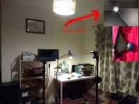
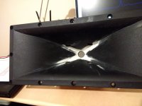
I have been measuring this driver and horn combination:
Product - Pro Audio Components
Product - Pro Audio Components
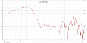
My measurement environment is far from ideal, as the horn exhibits directivity I am assuming no reflection from the rear wall, looking at the impulse response my first major reflection is at 8.5mS which corresponds to 3m (distance from front of horn to wall and back to microphone). Its too late right now to measure loudly and take the light shade off.
I have measured two of driver+horn to see if they are consistent. For all measurements input voltage was 2.83V and the microphone was 1m away on axis.
I'm not sure on a few things:
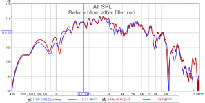
1. Are the harmonic distortion figures I'm getting normal? I see around 2-3% THD in the operating band. I know that psycoacousticly this is fine but I don't know how this compares to other 1" compression drivers.
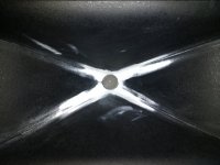
2. The horn has an abrupt transition from square profile to round this causes diffraction, is this the likely cause of the boost in the 4-10k band? should I do something about smoothing this? I was thinking wood filler.
3. looking at the distortion curves I think I want to cross using a 24dB/octave filter @ 1.5Khz to my mid range, is this sensible? this is for a PA application as well as for use at home, however I won't ever need to go over 120dB peak/1m.
Product - Pro Audio Components
Product - Pro Audio Components
My measurement environment is far from ideal, as the horn exhibits directivity I am assuming no reflection from the rear wall, looking at the impulse response my first major reflection is at 8.5mS which corresponds to 3m (distance from front of horn to wall and back to microphone). Its too late right now to measure loudly and take the light shade off.
I have measured two of driver+horn to see if they are consistent. For all measurements input voltage was 2.83V and the microphone was 1m away on axis.
I'm not sure on a few things:
1. Are the harmonic distortion figures I'm getting normal? I see around 2-3% THD in the operating band. I know that psycoacousticly this is fine but I don't know how this compares to other 1" compression drivers.
2. The horn has an abrupt transition from square profile to round this causes diffraction, is this the likely cause of the boost in the 4-10k band? should I do something about smoothing this? I was thinking wood filler.
3. looking at the distortion curves I think I want to cross using a 24dB/octave filter @ 1.5Khz to my mid range, is this sensible? this is for a PA application as well as for use at home, however I won't ever need to go over 120dB peak/1m.
Attachments
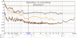
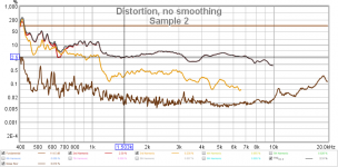
1. Yes. they are normal. All compression drivers have dominant 2nd harmonic. 3th harmonic less than 0.5% is OK.
2. Find smaller and better horn.
3. Cross it at 1.8 kHz, better yet at 2 kHz.

2. Find smaller and better horn.
3. Cross it at 1.8 kHz, better yet at 2 kHz.
Ha, don't make me laugh! Of course you will!this is for a PA application as well as for use at home, however I won't ever need to go over 120dB peak/1m.
I would actually like a bigger horn as I am going to drill some holes for 4*faital pro 3FE25 to fire into the horn. I'm planning to use them down to 400Hz, the horn is far too small to load them this low but there will be efficiency gain higher in frequency, the combination should behave as a point source and allow me me the get the horn acoustically close to a 15" midbass. I do own some larger ZXPC 18” horns for 2” drivers but am saving them for another project.
I have added some wood filler to smooth the transition, the only notable change I’m seeing is increase output 18-20kHz. I would guess if I could measure the polar response this would correspond to reduced off axis output in this range as I have reduced a source of diffraction. If this is true I would ***** this as a positive change as the directivity will be monotonic which is considered desirable. If I were not modifying the horn anyway this would probably not be worthwhile doing as you can see it now requires repainting.
I don't anticipate having to provide sound beyond 10m with this speaker which would still be 100dB peak which is loud enough. By 18kHz sensitivity is down to 90dB/2.83V/1m anyway so hitting that kind of level is only going to happen in the mid band without over powering the speaker. Most of the time this will be used indoors with less than a watt.
Attachments
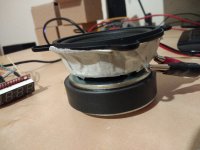
I have a WT3 now so time to begin work on the Faital pro 3FE25. I am using 4 of them per horn and would like to cross them to the compression driver as high as possible.
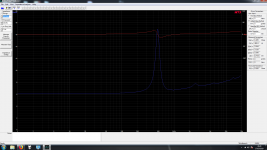
To do this I need to minimize the rear sealed volume. The plan with this is to construct the rear chamber using paper mache. The rear chamber volume can be found for simulation purposes by observing the change in resonant frequency. I have prototype'd this with painters tape: Free air: 114=Hz, tape=572Hz. You can see from the impedance sweep there are some anomalies caused by incomplete sealing, however I am pretty confident this is going to be a viable method for getting a high quality sealed back midrange.
To do this I need to minimize the rear sealed volume. The plan with this is to construct the rear chamber using paper mache. The rear chamber volume can be found for simulation purposes by observing the change in resonant frequency. I have prototype'd this with painters tape: Free air: 114=Hz, tape=572Hz. You can see from the impedance sweep there are some anomalies caused by incomplete sealing, however I am pretty confident this is going to be a viable method for getting a high quality sealed back midrange.
Attachments
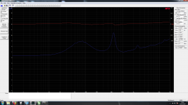
I added 3 layers of paper mache on top of the glue and some instant nails adhesive. As you can see from the impedance sweep the sealing has improved with no evidence of the free air resonance. The next stage is to model the midranges on the horn, after working backwards to find the rear chamber volume.
The closed mic measurement isn't calibrated. The -3dB looks to be around 380Hz which is great as this is my target crossover frequency to my LF driver.
The closed mic measurement isn't calibrated. The -3dB looks to be around 380Hz which is great as this is my target crossover frequency to my LF driver.
Attachments
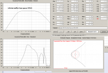
I have simulated the midrange mounted on the horn. What I am looking for here is that the cancellation null will be high enough in frequency. For some reason in simulation my drivers output is ~ 80dB/1W in hornresp (for a large box) while FaitalPRO give sensitivity as 91dB/1W. I do hope I can add 11dB to these sims otherwise I'm not going to hit my SPL target! (120dB/1m). The sims look OK I think to cross at 1.5kHz, the cancellation notch will be a bit lower in frequency as I haven't included the compression driver.
Maximum SPL is limited by driver input power to ~124dB continuous assuming that the sim 11dB down and multiplying the number of driver by 4 increases the SPL by +12dB.
Maximum SPL is limited by driver input power to ~124dB continuous assuming that the sim 11dB down and multiplying the number of driver by 4 increases the SPL by +12dB.
Attachments
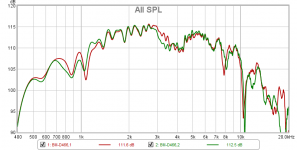
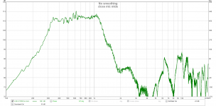
I don't have time to write up everything I have done right now but I am excited enough about this measurement to post it immediately. This is the 2.83V sensitivity of the nominal 8ohm load of 4 mids mounted on the horn. This is above 100dB/1W from 337Hz to 1.34 kHz. I would have preferred them to get a bit higher in frequency to meet the compression driver as it would make the crossover easier. As it stands if I aimed to an acoustic crossover at 1.3kHz this should (just about) work.
Attachments
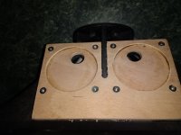
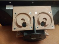
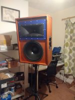
I now have some time so will explain the mechanical attachment of the midranges.
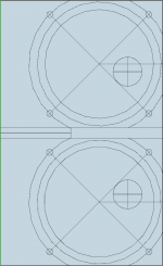
To attache the midranges I constructed two identical mounting plates per horn (top and bottom). These mounting plates are made up of two sheets of ~6mm plywood (more like 5.5 mm in practice), that are glued together using wood glue. I constructed both the top layer and bottom layer of the mounting sheets using the same template that is attached. The procedure for using the template is as follows:
1. Stick on and cut around template and mark with small drill hits the center of the midrange taps.
2. Remove the template from this piece of ply (water effective), this is now the bottom sheet in the lamination.
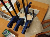
3. Stick on and cut around template and use 72 mm hole saw (available from downlight kit) to cut out driver holes. This is the top lamination.
3. Align sheets at bottom left corner, clamp and wood glue.
4. Use coping saw to cut out slot.
4b. I think mounting the horn will be easier if 15mm is removed from the front of the template which I have done to one of the mounted plates pictured and plan to do on other future plates. I would advise doing this at this point for maximum mechanical rigidity in earlier steps.
5. Drill through driver mounting hole locations with 6mm drill bit
6. Screw in M4 threaded inserts (10mm depth type)
7. Epoxy plate to horn. The back of the mounting plate should be aligned with the end of the flat part of the horn.
8. Use 19 mm wood bit to complete driver taps using previously marked locations in step1. I did this very slowly and stuffed newspaper in the horn so that when breaking through I didn't gouge the horn.
I measure the midrange tap centers as 55 mm from the horn throat.
To attache the midranges I constructed two identical mounting plates per horn (top and bottom). These mounting plates are made up of two sheets of ~6mm plywood (more like 5.5 mm in practice), that are glued together using wood glue. I constructed both the top layer and bottom layer of the mounting sheets using the same template that is attached. The procedure for using the template is as follows:
1. Stick on and cut around template and mark with small drill hits the center of the midrange taps.
2. Remove the template from this piece of ply (water effective), this is now the bottom sheet in the lamination.
3. Stick on and cut around template and use 72 mm hole saw (available from downlight kit) to cut out driver holes. This is the top lamination.
3. Align sheets at bottom left corner, clamp and wood glue.
4. Use coping saw to cut out slot.
4b. I think mounting the horn will be easier if 15mm is removed from the front of the template which I have done to one of the mounted plates pictured and plan to do on other future plates. I would advise doing this at this point for maximum mechanical rigidity in earlier steps.
5. Drill through driver mounting hole locations with 6mm drill bit
6. Screw in M4 threaded inserts (10mm depth type)
7. Epoxy plate to horn. The back of the mounting plate should be aligned with the end of the flat part of the horn.
8. Use 19 mm wood bit to complete driver taps using previously marked locations in step1. I did this very slowly and stuffed newspaper in the horn so that when breaking through I didn't gouge the horn.
I measure the midrange tap centers as 55 mm from the horn throat.
Attachments
Last edited:
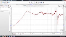
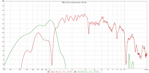
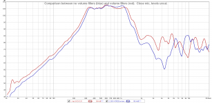
Here are the impedance and frequency responses. I have quite a lot of reflection issues at lower frequencies. But I don't have a better environment to test in easily. This is more noticeable in the mid range as the horn isn't as directive. The mids are wired as series parallel to make an 8 ohm load.
I have also taken a close mic measurement of the mids (at the horn mouth), I think that it shows that there HF bandwidth is been limited by the volume of the air under the cone and so will attempt to build volume filling plates tonight.
I have also taken a close mic measurement of the mids (at the horn mouth), I think that it shows that there HF bandwidth is been limited by the volume of the air under the cone and so will attempt to build volume filling plates tonight.
Attachments
I added some volume reduction plates to the woofer pads. Its late so I can only do close mic measurements. They show a modest increase in bandwidth ~100Hz.
The volume under the woofer cone has been decreased to almost the minimum possible it looks to me that that the limit on the mids high frequency output is due to their location on the horn. A few mm reduction in distance is possible but little more so this looks to be the best that this horn will do. It's a good job the compression driver looks to be able to go low.
With plug:
mid level: 106.33
-3dB (high): 1.286k
-6dB (high): 1.35k
-3dB (low): 305 Hz
-6dB (low): 285 Hz
Without plug:
mid level: 106.36
-3dB (high): 1.194k
-6dB (high): 1.254k
-3dB (low): 320
-6dB (low): 305
differences:
+92Hz (-3dB high)
+96Hz (-6dB high)
-15Hz (-3dB low)
-20Hz (-6dB low)
Attachments
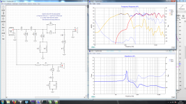
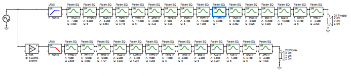
I have designed a passive crossover for the horn using 3.5mS gated measurements. I have to say the combination of REW and xsim is sublime. The crossover has been designed for 120dB quasi continuous output. By which I mean that in the worst case at 120dB the resistors get 3x there rated power at specific frequencies. So it would be possible to destroy the crossover with a full power sine wave at precisely the right frequency that was sustained for many seconds. Compared to most other speakers this is a vast over rating. All other components are continuous rated. It should not be possible to destroy the speaker with music unless exceeding 120dB/1m average at which point the drivers are in danger.
The crossover uses the 4th order acoustic roll off on the mids and adds a 4th order electrical roll off to the tweeter. The crossover frequency is 1.5kHz, the tweeter is rated for 1.8kHz with a 2nd order crossover so this should be fine. This is only the 2nd passive crossover I have designed so I'm sure I have missed some tricks. The crossover to the bass driver may move up to 500Hz from the target 400Hz, I have to run the numbers on the vertical dispersion, the bass driver crossover (at least at first) will be done actively using a symetrix symnet 8x8 DSP.
I would post the simulations here but they are 4mB so I don't think I can do so directly, ask me if you want them...
Attachments
Excellent looking work on the mounting plates, cone volume fillers!
Don't forget that while a large horn measured in isolation will exhibit good pattern control, what matters is the entire system integration with the other elements on a baffle.
Spaced woofers in an MTM on a baffle can increase the directivity of the horn downward in frequency.
Don't forget that while a large horn measured in isolation will exhibit good pattern control, what matters is the entire system integration with the other elements on a baffle.
Spaced woofers in an MTM on a baffle can increase the directivity of the horn downward in frequency.
Excellent looking work on the mounting plates, cone volume fillers!
Don't forget that while a large horn measured in isolation will exhibit good pattern control, what matters is the entire system integration with the other elements on a baffle.
Spaced woofers in an MTM on a baffle can increase the directivity of the horn downward in frequency.
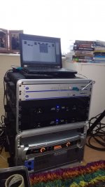
I actually completed the speakers and have been using them at parties with lots of positive comments and as my home Hi-Fi. However I haven't had a chance to do decent measurements on the whole speaker, which has delayed my posting. I am using the Beyma 15 CM V2 as the bass driver crossed at 500 Hz bass reflex with a slot port at the top of the cab. The subs cross in at 120Hz usually. I'm using 120W/channel amps and reach clipping point on the amplifiers before distortion is noticeable. I'm thinking about going up to ~500W per channel but will need to implement rigours limiting.
The highlights for me so far has been hearing live vocals through the system which sound completely uncoloured and the projection of sound with distance. At one point I was 150m away from the system and it still sounded clear which I think is a characteristic of point source systems? I still have to totally dial the 500Hz crossover point based on polar responses but even a whole summer after finishing these speakers I'm very happy with the sound.
Attachments
Hi Kipman,
I've been playing with EQ /xo's on my horns and one thing I noticed was that the mids acoustic roll off is closer to a 6th order slope than a 4th order. (I'm assuming the bandpass gives a 4th order with an extra 2nd order from the drivers mass roll off ?)
So it kind of makes sense that I found a post of Tom D's post stating he uses 4th order electrical on the tweeters (combined with the CD's 2nd order roll off it would give an acoustic 6th order slope to match the mids)
Cheers,
Rob.
Attachments
Hi Kipman,
(I'm assuming the bandpass gives a 4th order with an extra 2nd order from the drivers mass roll off ?)
Cheers,
Rob.
Thought this morning maybe the acoustic notch rather than mass roll off was increasing the slope.
Ah yes I see Rob, yes my slopes don't match despite what I said last year which might explain the ~2.5dB drop in output around the crossover. From the lines you drew I get -36dB/octave for the mids (6th order) and +22dB/octave for the tweeter (~4th order). This is not likely to be noticeable in the finished speaker however as as its DSP equalized.
The cancellation notch should be around 3kHz so I think the steeper roll off must be due to the mass. However it would seem exceptionally difficult to get all the various effects to line up such that both drivers had 6th order rolloffs with matched -6dB points. Further complicating this is that the raw driver responses don't exactly look like textbook bandpass filters!
Perhaps the best way of thinking of crossovers in MEHs is the end result? we want maximum output at the crossover, driver protection and attenuation of out of band resonances. There are not the polar pattern modification results that conventional flat baffle speakers have. This crossover seems to succeed in the first two but perhaps the 4kHz peak in the mids output (which will be a nasty resonance) only 10dB below the speaker output is audible? so perhaps it would be better to add an electrical rolloff to the mids to attenuate that peak? even if it makes the response less flat. going up to 8th order slopes would seem a bit nuts both in number of components and keeping everything in tolerance but would be possible in DSP that allows entry of custom biquads.
Last edited:
Yep I've been reading up on the xo for my meh for a while and there does seem to be some conflicting info out there. The mids do seem to use their acoustic slopes for the crossover, with low order slopes used to provide excursion protection on the low end and attenuation of the resonances on the top end. I think something about trying not to upset the phase in its passband.
I've read tom d state that he uses an electrical 4th order or higher on the tweeters, but think there is already a 1st order high pass up near 10k to compensate the CD a bit.
However other people are saying there is only a 1st order on the CD.
Like you say, maybe I just need to aim for a smooth response and not be worrying so much.
Cheers,
Rob.
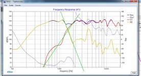
Results
I did take some on axis measurements in December of the finished project, I was hoping to be able to make full polar balloons but the weather was an issue. I'm building a battery powered amp solution at the moment so may be able to get measurements more easily in future (I don't have a garden).
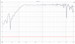
The first plot is the raw on axis 'driver' responses inline with the tweeter (which includes the mids, comp and passive crossover). These results are gated to get rid of the effect of reflections, for the woofer an ungated but smoothed response is also included to show the bass performance.
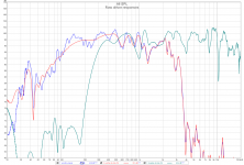
The second plot is the simulated result of the large number of PEQs (also attached), LR48 and time alignment. I measured the time alignment using the raw UMIK-1 responses and was a bit skeptical that the timing would remain the same. However extensive testing in my living room with different delay values and pink noise have confirmed this is in fact correct and the timing did stay consistent between sweeps.
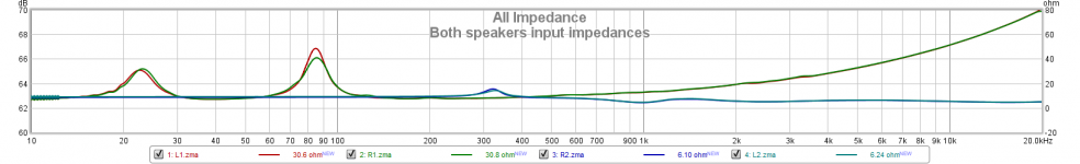
The 3rd plot is the impedance of the two speakers at their inputs. We can see from the woofer impedances that the tuning has come out at around 40Hz a bit lower than expected probably due to the high aspect ratio of the slot port. If the tuning was higher the output in the 80 - 100 Hz range could be increased however this low tuning does make the tops more amenable to EQ to bring in some bass if operating without subs. When I run them with subs (almost all the time) they are crossed at 120Hz where the port is having very little effect.
I did take some on axis measurements in December of the finished project, I was hoping to be able to make full polar balloons but the weather was an issue. I'm building a battery powered amp solution at the moment so may be able to get measurements more easily in future (I don't have a garden).
The first plot is the raw on axis 'driver' responses inline with the tweeter (which includes the mids, comp and passive crossover). These results are gated to get rid of the effect of reflections, for the woofer an ungated but smoothed response is also included to show the bass performance.
The second plot is the simulated result of the large number of PEQs (also attached), LR48 and time alignment. I measured the time alignment using the raw UMIK-1 responses and was a bit skeptical that the timing would remain the same. However extensive testing in my living room with different delay values and pink noise have confirmed this is in fact correct and the timing did stay consistent between sweeps.
The 3rd plot is the impedance of the two speakers at their inputs. We can see from the woofer impedances that the tuning has come out at around 40Hz a bit lower than expected probably due to the high aspect ratio of the slot port. If the tuning was higher the output in the 80 - 100 Hz range could be increased however this low tuning does make the tops more amenable to EQ to bring in some bass if operating without subs. When I run them with subs (almost all the time) they are crossed at 120Hz where the port is having very little effect.
Attachments
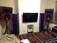
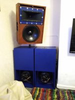
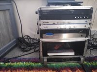
action shots
Here are some pictures of the speakers in use and their companion subs and amp rack, since the earlier pictures I added magnets for removable transport grills, I find the grills very deterious for sound quality so take the risk of leaving them off when in use. Its always pretty hectic or dark when they get to play out so I tend not to get photos but I have had quite a lot of DJs and local bands play through the system.
Here are some pictures of the speakers in use and their companion subs and amp rack, since the earlier pictures I added magnets for removable transport grills, I find the grills very deterious for sound quality so take the risk of leaving them off when in use. Its always pretty hectic or dark when they get to play out so I tend not to get photos but I have had quite a lot of DJs and local bands play through the system.
Attachments
That's come out well with the passive. Plus/minus 3dB pretty much all the way through. Nice!
I have some Fane bass drivers that have a very similar response as your bass drivers. I considered taking a bit off the ports to raise the tuning, but like you decided that a lower tuning can be fettled with dsp.
Cheers,
Rob.
I have some Fane bass drivers that have a very similar response as your bass drivers. I considered taking a bit off the ports to raise the tuning, but like you decided that a lower tuning can be fettled with dsp.
Cheers,
Rob.
- Home
- Loudspeakers
- Multi-Way
- BM-D446 on PH-4220