Hey guys,
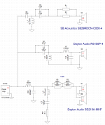
I messed around with a 3-way speaker design and its crossover. I "designed" the crossover with XSim. Since this is my first ever designed crossover, it would be great to get some feedback on how to improve the crossover design. I use the following drivers:
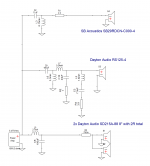
Sub: 2x Dayton Audio SD215A-88 in parallel
Mid: 1x Dayton Audio RS150P-4A (mid)
High: 1x SB Acoustics SB Acoustics SB29RDCN-C000-4 (high)
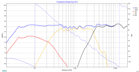
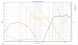
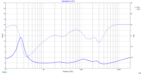
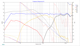
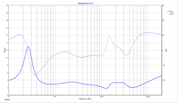
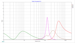
Attached you will find the crossover schematic, frequency response and impedance of the designed crossover. I also attached an image of the frequency response including the phases of each speaker.
Here are some questions from my point of view.
1. I'm aware of the fact that the impedance is to low. But can I raise the impedance without putting a resistor in series?
2. I don't like the midrange speaker because its frequency response has to much ripple. But would this ripple be audible?
3. I tried to match the phases of the speakers at the crossover points. This went well for the sub-mid crossover but not very well for the mid-high crossover. How does the phase mismatch can affect the sound?
4. Reviewing the mid-woofer frequency response, a little spike in the down-slope at around 5kHz-6kHz is noticeable. From my understanding, this is called cone breakup, right? I've read that operating the speaker at cone breakup leads to an increased distortion which has to be avoided. Should the spike be damped by another notch filter?
5. What about the phase of the impedance plot? I guess that phase response has to meet some criteria to not disturb the amplifiers feedback network. Are there any golden rules for the electrical phase response?
I would love to hear from you guys.
Greetings
I messed around with a 3-way speaker design and its crossover. I "designed" the crossover with XSim. Since this is my first ever designed crossover, it would be great to get some feedback on how to improve the crossover design. I use the following drivers:
Sub: 2x Dayton Audio SD215A-88 in parallel
Mid: 1x Dayton Audio RS150P-4A (mid)
High: 1x SB Acoustics SB Acoustics SB29RDCN-C000-4 (high)
Attached you will find the crossover schematic, frequency response and impedance of the designed crossover. I also attached an image of the frequency response including the phases of each speaker.
Here are some questions from my point of view.
1. I'm aware of the fact that the impedance is to low. But can I raise the impedance without putting a resistor in series?
2. I don't like the midrange speaker because its frequency response has to much ripple. But would this ripple be audible?
3. I tried to match the phases of the speakers at the crossover points. This went well for the sub-mid crossover but not very well for the mid-high crossover. How does the phase mismatch can affect the sound?
4. Reviewing the mid-woofer frequency response, a little spike in the down-slope at around 5kHz-6kHz is noticeable. From my understanding, this is called cone breakup, right? I've read that operating the speaker at cone breakup leads to an increased distortion which has to be avoided. Should the spike be damped by another notch filter?
5. What about the phase of the impedance plot? I guess that phase response has to meet some criteria to not disturb the amplifiers feedback network. Are there any golden rules for the electrical phase response?
I would love to hear from you guys.
Greetings
Attachments
A1, many amps can drive 2 ohm loads. However I think the 0.1mH inductor in your tweeter section may be causing the impedance to dip below 2 ohm. If that inductor can be increased great but if not I wouldn't worry too much about it.
A2, I would say it is very good. Is it measured in-situ? (Measured in the actual cabinet.)
A3, I see a 90 degree difference which is a Butterworth alignment - great sounding. This is good. Again is this measured in-situ?
A4, You have already attenuated it by 15dB. That might be enough for a paper woofer but I don't have enough experience with that to be able to give a firm answer... sorry.
A5, Your phase plot looks like a normal speaker so don't see why any amp wouldn't be happy to drive this, but then I have not heard about any rules saying that the phase must have a certain relationship to make the amp happy. I am guessing, just guessing, that maybe purely inductive or purely capacitive loads are harder, but you have nothing like those here. Maybe you could introduce me to what you have found on this topic so far.
You don't want to put a resistor in series to raise the impedance. Your problem with the woofers is the large capacitor after the coil. It's way too big and dropping the impedance way too much. You could try putting a couple of ohms in series with the shunt cap, but that won't necessarily work very well.
On the tweeter, a similar issue, big cap followed by a shunt coil. You need a smaller cap before the shunt coil. probably no more that maybe 5.6uf
I suspect similar issues on the mid.
Tony.
On the tweeter, a similar issue, big cap followed by a shunt coil. You need a smaller cap before the shunt coil. probably no more that maybe 5.6uf
I suspect similar issues on the mid.
Tony.
1. 2-ohm impedance is dangerously low for most amplifiers. Use only one SD215A-88 with DVC in parallel - total impedance will be 4-ohm nominal. Or, use two woofers with voice coils in parallel-serial configuration to get 8-ohm nominal impedance (sensitivity will be the same). Carefully choose L5 and C8 to retain maximum SPL sensitivity, but, most importantly - maintain high enough impedance (above 3 ohms for one woofer). RLC branch R7, C7 and L4 drops impedance and generally is not required here. Eradicate R3 thru R6.
Tweeter filter is not optimal - too low impedance. C1-C3 seems too large and L1 too small - leading directly to very low impedance.
Tweeter filter is not optimal - too low impedance. C1-C3 seems too large and L1 too small - leading directly to very low impedance.
")
@cyberstudio:
Nope, this is just from the given frd and zma files from parts express and the dropbox of impulse audio (this is his youtube channel).
@wintermute:
I didn't consider the DVC of the SD215A. For the ZMA file available the DVC is wired in parallel, resulting in 2R for two speakers in parallel.
@giralfino:
You are right, I only used the open baffle frd and zma files from PE. At the moment I just try to learn with these as I don't have measurement equipment yet. What about the delay u mentioned?
Concerning the series resistors, I know this is not the best solution but the speaker is designed to be quite efficient. At around 10W@4Ohm I get 99dB SPL (Xsim) which is more than needed for a normal listening experience (I guess).
Attached you can find my current design. I changed the mid-range to a Dayton Audio RS125-4.
Although I was able to simplify the tweeters high-pass filter to 2nd order, the mid-range driver needed a damping resistor in the high-pass filter capacitor branch and an additional notch filter for damping a resonant peak at 1.5kHz.
The impedance improved a little bit but still isn't great.
Attachments
You have made a rod for your own back with such high efficiency and 4 ohm drivers. Why are you even doing this?
3 ways are difficult enough on impedance even when you can use some resistors to up the impedance.
Two 4 ohm basses in series, if you must, might work out a lot better. It will then be lower efficiency and you can get better impedance.
SEAS-3-Way-Classic
Polarity on 3rd order tweeter and second order mid is usually the same if you've got the time-alignment correct. +-- overall. If you ever see +-+, that is often stepped baffle 2nd order slopes.
One of the tricks to up impedance on the troublesome mid section is to use a smaller input capacitor and a bigger shunt coil.
Those are infinite baffle measurements. You don't really need measurement equipment in order to simulate the baffle step and diffraction effects, you only need proper software tools. If you don't simulate those effects all your XSim simulation is totally wrong. The question about low impedance is still valid as it is general, but do yourself a favor and learn how to simulate the baffle step before using XSim. Have a look at the pdf at "How to Design Loudspeakers without Performing Measurements": softwareYou are right, I only used the open baffle frd and zma files from PE. At the moment I just try to learn with these as I don't have measurement equipment yet. What about the delay u mentioned?
As for the delay, due to simple geometry, the sound from the mid arrives to you after the sound of the tweeter. This is a combination of the fact that the tweeter will be at ear level and the mid not, and the fact that the mid emits the sound something behind the baffle. The delay value depends thus on where you place the drivers on the baffle and the dimension on the mid (bigger, the sound comes from further away). My measurement on a speaker with the RS125P and ND28F drivers showed 0.76" of delay, whereas a speaker with the 830883 and 27TBFCG drivers showed 1.4" of delay. Those delays seem small, but they aren't at the wavelength of the crossover point.
Ralf
- Status
- This old topic is closed. If you want to reopen this topic, contact a moderator using the "Report Post" button.
- Home
- Loudspeakers
- Multi-Way
- Review of my crossover design