I have made a set of 2-way bookshelf speakers using the drivers from a project i made some 15 yars ago. The drivers are Peerless DT105h and CSX145. The filters i use now are very simple. I want to upgrade them to get a flatter frequency response. I have started to simulate the filter in XSim but since I am new to this I probably did a lot wrong...
-Is the impedance to low?
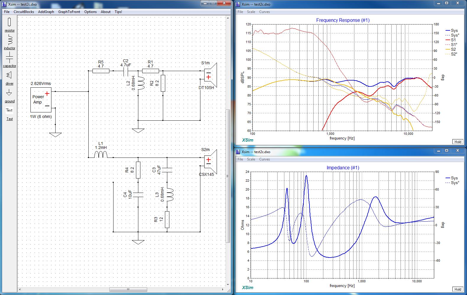
-Is there going to much current to ground in the bass filter?
-Is the roll off of the bass steep enaugh.
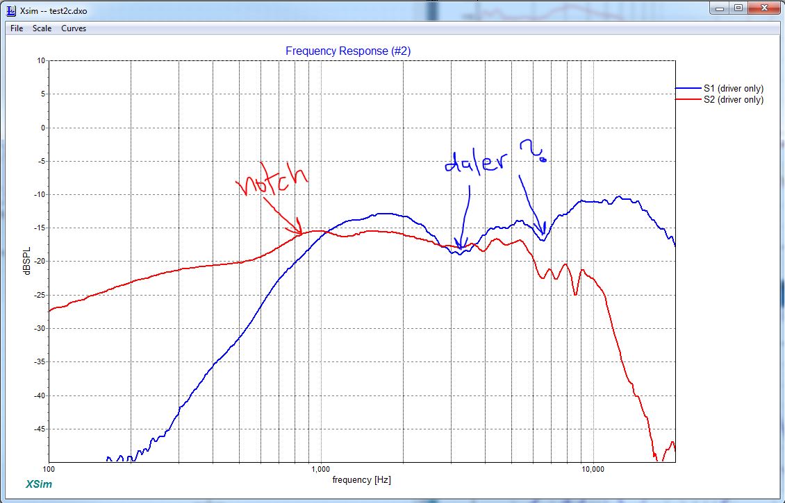
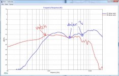
-Why do I have two deep valleys (marked "daler") in the treble curve at 3k and 6.5k?
-Should I add two resistors in series for R3?
I would appreciate some tips and guidance")
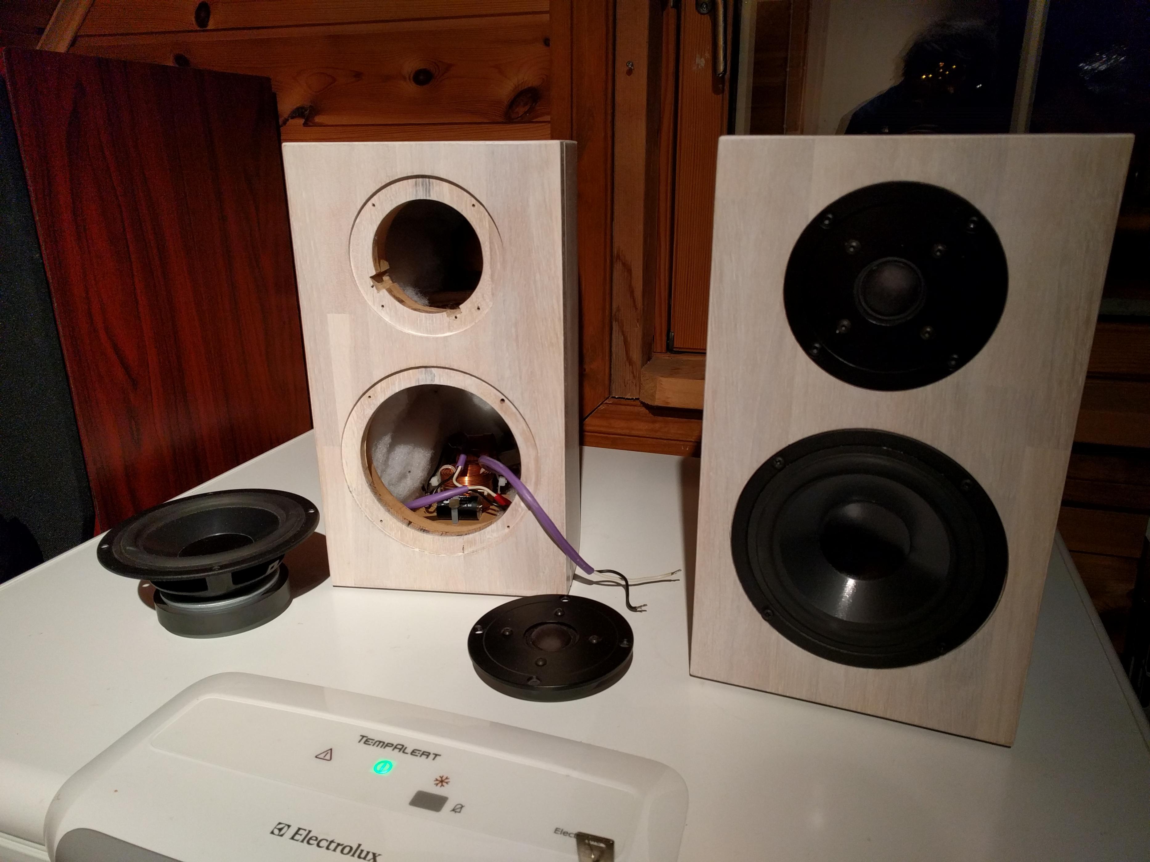
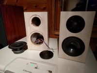
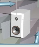
The speakers look like this:
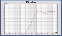
The frequency response in my living room for each driver is like this (no filter):
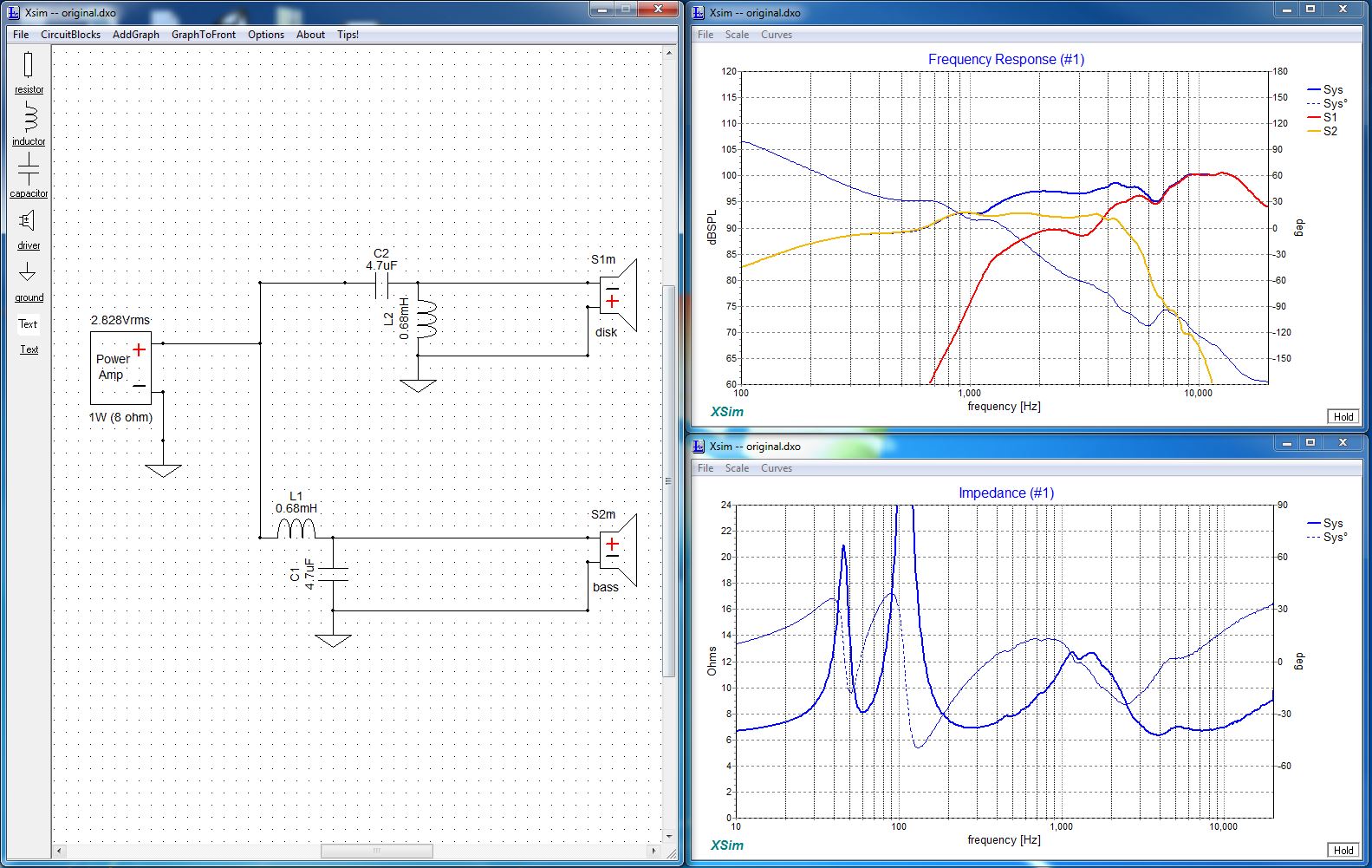
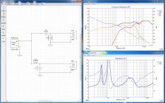
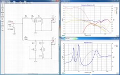
The filters I use now is just simple 2nd order crossovers with no attenuation at all. like this:
My current filter design in XSim. (I have tried to reuse some components I already have)
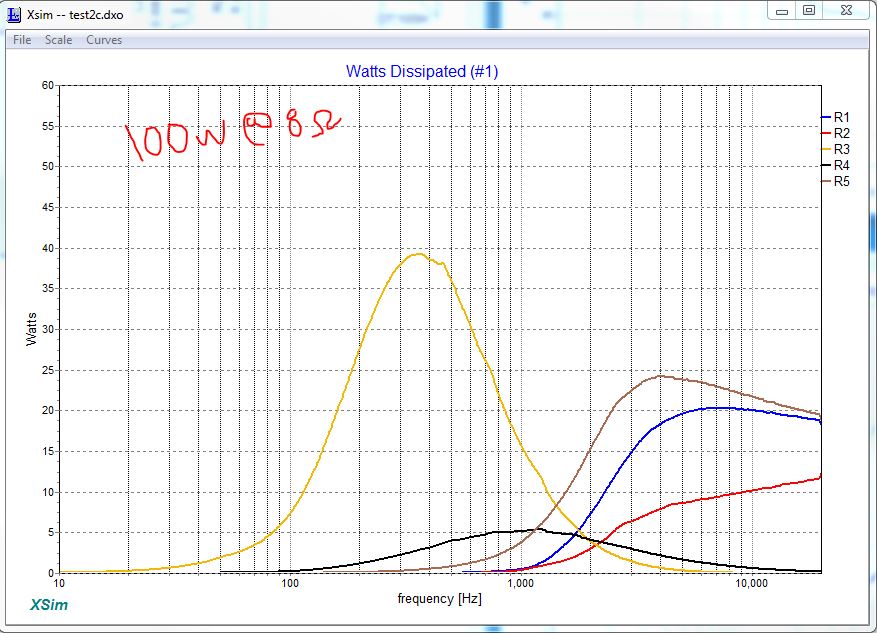
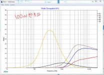
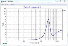
The prower across the resistors:
-Is the impedance to low?
-Is there going to much current to ground in the bass filter?
-Is the roll off of the bass steep enaugh.
-Why do I have two deep valleys (marked "daler") in the treble curve at 3k and 6.5k?
-Should I add two resistors in series for R3?
I would appreciate some tips and guidance
The speakers look like this:
The frequency response in my living room for each driver is like this (no filter):
The filters I use now is just simple 2nd order crossovers with no attenuation at all. like this:
My current filter design in XSim. (I have tried to reuse some components I already have)
The prower across the resistors:
Attachments
Perhaps you could start by stating what the measurement conditions were, or better start all over again. Drivers are good quality so there should be no bad surprises.
- put one loudspeaker, with drivers and stuffing/lining in place, in the room far away from everything
- mic in the tweeter axis 1 m away
- set the required volume and let it remain the same during measurements, mic stays in the same spot
- record tweeter FR only, gating set to a couple of ms
- record woofer FR only, gating set to 15 ms
- record (tw+w) FR only, wired in parallel, we will use it for delay calculation
- record tw impedance
- record woofer impedance in the enclosure, stuffing/lining in place
- note down baffle measures and driver position,
- export measurement files as textual files (zma,frd), zipped. Attach these separately if exceeding file size limit forum allows.
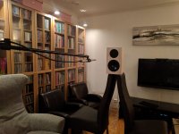
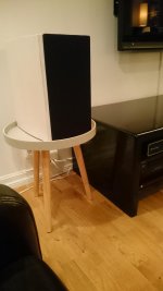
The FR measurements was taken in my living room as far away from walls and furniture as possible. (the picture is not the final measurement setup, but it is similar) The speaker was at 1,5m from the floor and mic was 1m from the speaker in line with the center of the speaker (between bass and treble).
All measurements was in the box, drivers connected directly to the amp.
All measurements was in the box, drivers connected directly to the amp.
Attachments
I did not take a FR tw+w parallel measurement, but if it is important I can make one.
For imp measurement i used ARTA (Limp) and for FR measurement I used HOLMimpulse. Tested both sine sweep and square noise signal with quite similar response. I also tested two different speaker positions to check if these bumps was room-related.
My measuring hardware is a EMC8000 mic and a Roland Duo Capture EX sound card/mic amp. For the imp measurement i used the ARTA measuring box
Thank you for the data so far. Do you remember what the window gating was that you used for measuring woofer? I can see that you used delay for both of the drivers in XSim. Can you check what these values are?
Out of curiosity, try to record tweeter FR from perhaps 40 cm away on-axis and a second measurement like 30 deg to the right. Let us see what that might look like. Keep the gating such that the whole Impulse is within it.
Out of curiosity, try to record tweeter FR from perhaps 40 cm away on-axis and a second measurement like 30 deg to the right. Let us see what that might look like. Keep the gating such that the whole Impulse is within it.
Ok, under some assumptions, this is the filter I would count on. Since we don't know where this HF rise is coming from, tweeter or perhaps microphone, the R4=10R can be reduced incrementally to 8.2R, 6.8R, 5.6R etc. to accomodate your own perference.
Attachments
Hi
Thanks for the design!
So third order on the tweeter and second order on the bass. I Don't know what the rise/bumps (depends how you see it) in the tweeter response is.
But one thing I noticed in your design is that the power across R2 (R5 in my copy) is very high. Is this a problem? The source is set to 100w @ 8ohm
Attachments
Hello,
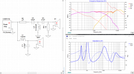
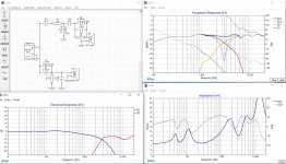
The dips in the tweeter response are caused by diffractions of the tweeter in this little cabinet with sharp edges.
I did a simulation in Leap of your tweeter in that cabinet.
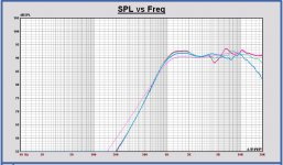
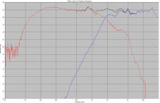
In the first plot you see:
- the infinite baffle response of the tweeter model in Leap - pink curve
- the full space response of the tweeter at 0 degrees, 15 and 30 degrees off axis horizontal - red, green and blue curve.
You can see the impact of the cabinet and the strong deviations on and off axis.
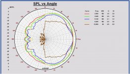
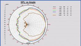
In the polar diagram you can see even better the non-uniform response in the horizontal plane (polar responses are normalized to the on axis response).
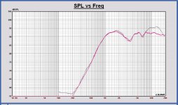
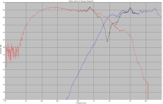
Very strange in your tweeter measurement is the SPL boost above 6kHz. Like Lojzek is mentioning also, you have to investigate what the reason is of this boost, measurement, tweeter itself ... and adapt your filter in the correct way. See in the plot the tweeter response based on the data sheet data (red curve) versus your measurement (grey curve)
Regards, Paul
The dips in the tweeter response are caused by diffractions of the tweeter in this little cabinet with sharp edges.
I did a simulation in Leap of your tweeter in that cabinet.
In the first plot you see:
- the infinite baffle response of the tweeter model in Leap - pink curve
- the full space response of the tweeter at 0 degrees, 15 and 30 degrees off axis horizontal - red, green and blue curve.
You can see the impact of the cabinet and the strong deviations on and off axis.
In the polar diagram you can see even better the non-uniform response in the horizontal plane (polar responses are normalized to the on axis response).
Very strange in your tweeter measurement is the SPL boost above 6kHz. Like Lojzek is mentioning also, you have to investigate what the reason is of this boost, measurement, tweeter itself ... and adapt your filter in the correct way. See in the plot the tweeter response based on the data sheet data (red curve) versus your measurement (grey curve)
Regards, Paul
Attachments
Last edited:
How many watts you think you are realistically putting into that speaker? (Or more precisely, how many volts your amp will safely provide to the speaker, before getting too loud).But one thing I noticed in your design is that the power across R2 (R5 in my copy) is very high. Is this a problem? The source is set to 100w @ 8ohm
Ralf
The dips in the tweeter response are caused by diffractions of the tweeter in this little cabinet with sharp edges.
Thanks a lot for this tip!
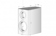
Initially I planned to bevel the edges on the sides like on the CAD drawing attached in the third post. Do you think this would affect the dips in a positive way?
Normally I have a fabric front attached. I guess this also would affect this. I never measured with these on, but i'll do that the on the next measurement.
How many watts you think you are realistically putting into that speaker?
I know that 100W all over the frequency range is not likely. I just use this number as a reference when i check the load on all resistors, an in the desingn from Lojzek this value is very high compared to other designs I have tested. But I don't know if it is a problem since I am new to this...
Attachments
Last edited:
My current speakers have a resistor in the tweeter filter like here. When I finalized it I put the crossover outside the cabs, run hard the speaker for a lot and touched the resistor. It wasn't even warm, despite being a 5W resistor. Off course running hard is relative, in my case it was surely no more than 20W, as my amp is a 40W one, but in my living room that was loud. For your mental safety put a 20W resistor and forget about it.
Ralf
Ralf
...But one thing I noticed in your design is that the power across R2 (R5 in my copy) is very high. Is this a problem? The source is set to 100w @ 8ohm
Hey there, it would not present a problem to me and the way I use loudspeakers. Assuming you were to feed such of an input voltage, I guess a burned resistor would have been the least of your problems, beside fried or mechanically damaged drivers. You can resort to multiple resistors or a single higher wattage value part, a heatsinked resistor, whatever makes you feel safe.
A bevelbox has a more uniform SPL of course.
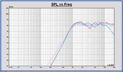
I simulated the SPL with such bevelbox. Edges are 20mm wide. So the flat front reduces to 140mm x 280mm, edges are 45 degrees.
Comparing the bevelbox with the rectangular box, the SPL behavior becomes much more uniform below 5kHz and also off axis. You can see in the plots.
First plot is the SPL of bevelbox (red curve) versus rectangular box (grey).
Second plot, the SPL on infinite baffle (pink) and the full space on axis and 15, 30 degrees horizontal off axis responses of the bevelbox.
And the polar response of the bevelbox.
Making the edges more rounded will become even better I suppose.
The impact of a tweeter placed close to the top of a cabinet with sharp edges, will always be visible. It is better to place the tweeter not too close to the top, but it isn't always possible to do it that way, like with this little cabinet.
Using a fabric front has its impact at high frequencies. You have to measure it, and choose if you like to optimize the SPL with the fabric front or not.
Attachments
Last edited:
If you prefer soldering over woodwork you may consider assembling a crossover circuit that will apply necessary corrections (at least in the measurement point). See example attached. Audio path difference between drivers was assumed (by guess) as 2 cm.
Attachments
If you prefer soldering over woodwork you may consider assembling a crossover circuit that will apply necessary corrections (at least in the measurement point). See example attached. Audio path difference between drivers was assumed (by guess) as 2 cm.
Recommended to add a resistor in series with C4 to avoid a short circuit C4 - C5 in the woofer filter at high frequencies.
Recommended to add a resistor in series with C4 to avoid a short circuit C4 - C5 in the woofer filter at high frequencies.
That's right, it's better not to leave it that way. A series resistor (3.3-4.7R) will improve the situation and introduce only neglectable changes on the stop band of the woofer.
Thanks for a lot of good input guys! I now have a couple of alternative crossovers. I will probably measure the FR once again with the front covers on and see how that will affect the tweeter response before deciding on the design since i rarely take these off. So it makes sense to design the crossover to be optimal with these on.
Also i have a bunch of crossover components laying around so if it is possible I will try to adjust the values so I don't need to buy all of them. (For Example i have two 1.2mH spools and the 1.8mH is quite expensive)
The rise in the tweeter could be the mic. http://www.cross-spectrum.com/cslmics/001_mic_report.pdf It looks like it has a rise of 2-3dB from 6k to 16k. I will try to load a calibration file before measuring.
And the amp and sound card isn't necessarily 100% flat either. I know that ARTA has a dual channel measurement to eliminate this but i think woking with ARTA is hard and I like HOLMimpulse a lot better but I don't know if dual channel is available in HOLMimpulse
It is easy to modify an existing inductor to a larger valued one. You should find some magnet wire off somewhere or use the wire from a smaller 0.25 mH inductor. You would attach the extra wire by soldering the ends of the two coils and wind some layer or two to the existing 1.2 mH. May be a couple of meters would have sufficed to become a 1.8 mH. This is more economic for keeping the dcr small than just adding another coil in series with it. You can use LCR meters, multimeters with some jig, ARTA like software and measure inductance in the process. I have my Clio connected constantly to the coil I wish to modify and observe the inductance changing while winding wire.
Hi there.
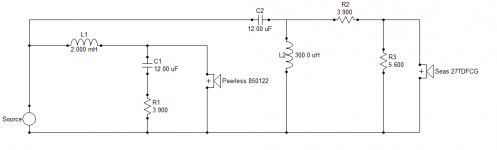
Looks like it's the AR.com Ed Frias DIY kit. I have one of those too. I think you'll need to go at least 1.8mH for BSC and adequate bass depending on room placement / back wall proximity. I've remodeled the crossover but replaced the Peerless tweeter with the better Seas 27TDFCG as per below.
Unfortunately, the 1.8KHz peak to 2.8KHz dip for the tweeter is an artefact of baffle diffraction and placement on the baffle. Rounding over corners doesn't materially impact this (my cabinet has roundovers). It's tweeter symmetry on the baffle. Having acoustic or golden ratio placement on a conventional baffle i find gives the smoothest ripple response. Jeff Bagby produced an excellent baffle diffraction simulator tool for this. When combined with the tweeters natural response - you can then customise for a flat on-axis response.
Attachments
- Status
- This old topic is closed. If you want to reopen this topic, contact a moderator using the "Report Post" button.
- Home
- Loudspeakers
- Multi-Way
- Redesigning filter, need help!