So I'm not finding what I need after looking around so I have to ask.
When loading two drivers into an offset horn, on opposing side of the horn, how is accurate compression ratio calculated? Is it from the theoretical front plan (mounting ring depth) of the driver or is it from the center of the cones (dustcaps)
Forgive my ignorance, help is always appreciated")
When loading two drivers into an offset horn, on opposing side of the horn, how is accurate compression ratio calculated? Is it from the theoretical front plan (mounting ring depth) of the driver or is it from the center of the cones (dustcaps)
Forgive my ignorance, help is always appreciated
I calculate it from the area where the drivers enter the horn.
For instance, if horn is rectangular and the horn throat enters the horn where the horn measures 10cm x 10cm, then the area of the horn at the throat is 100cm. (10 * 10)
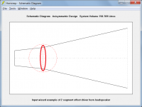
One thing that I've noticed "in the real world" is that you can get away with way higher compression ratios with offset horns. I think this is because the radiation from the driver expands in 360 degrees when the driver is mounted offset.
IE, if you have an 8" woofer and it's mounted at the apex of a horn with a coverage angle of 60 degrees, that woofer radiates into sixty degrees. If you take the same woofer and mount it offset in the exact same horn, the sound radiates into 360 degrees.
For instance, if horn is rectangular and the horn throat enters the horn where the horn measures 10cm x 10cm, then the area of the horn at the throat is 100cm. (10 * 10)
One thing that I've noticed "in the real world" is that you can get away with way higher compression ratios with offset horns. I think this is because the radiation from the driver expands in 360 degrees when the driver is mounted offset.
IE, if you have an 8" woofer and it's mounted at the apex of a horn with a coverage angle of 60 degrees, that woofer radiates into sixty degrees. If you take the same woofer and mount it offset in the exact same horn, the sound radiates into 360 degrees.
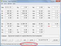
The compression ratio of a horn loudspeaker is defined using areas, not volumes. It is quite different to the volumetric compression ratio of an internal combustion engine for example. The compression ratio of the attached dual offset driver horn loudspeaker design is calculated as (2 * Sd) / S2. Given Sd = 350 cm2 and S2 = 400 cm2, the compression ratio with two opposing drivers is 1.75 : 1.
Attachments
Efficiency increases with higher horn compression ratios- that's not silly.
A 4/1 ratio might be too much too handle without buckling or folding for a thin cone driven to full excursion-breaking drivers or making them sound lousy could be thought of as silly. Using a flea-watt amp, the driver would not be damaged, and the extra efficiency makes for more dynamic range.
Ratios in excess of 4/1 can be used with many drivers with no problems- one has to look at particulars (and do some testing if it has not been done already) to determine what will work.
I tend to use higher ratios, partly because it's easier to get the center of a small hole closer to the HF driver's throat than to do it with a larger hole! But length and other variables have to be juggled. I also don't go for highest SPL, as that doesn't matter in my home applications and the midranges always have output to spare for that even with just a single driver mounted offset.
Humm. perhaps Olson was wrong...
This is what he wrote on the subject of horn efficiency:
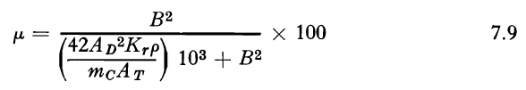
B = flux density (Gauss)
Ad= area of diaphragm (square centimeters)
Krp = resistivity of coil x density (a constant for the material used)
mc = mass of coil (grams)
At = area of horn throat
Chris
This is what he wrote on the subject of horn efficiency:
B = flux density (Gauss)
Ad= area of diaphragm (square centimeters)
Krp = resistivity of coil x density (a constant for the material used)
mc = mass of coil (grams)
At = area of horn throat
Chris
Attachments

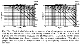
The effect of mass is discussed in part B of section 7.2 of Harry Olson's Acoustical Engineering text.
Here is an interesting visual of the effect of the real part of the horn efficiency (part A of section 7.2) showing that as the horn compression ratio increases, horn efficiency decreases:

Olson calls the term "42 Ad^2/At" the horn's "mechanical throat resistance", which is of course a function of the driver diaphragm area.
Chris
Here is an interesting visual of the effect of the real part of the horn efficiency (part A of section 7.2) showing that as the horn compression ratio increases, horn efficiency decreases:
Olson calls the term "42 Ad^2/At" the horn's "mechanical throat resistance", which is of course a function of the driver diaphragm area.
Chris
Attachments
I don't dispute the common wisdom that you can get higher HF output with a higher compression ratio and I suspect the formula doesn't either, given its simplifying assumptions and independence of frequency. My experience however is with offset drivers on Synergy horns and I know that there by changing the port area I'm merely tuning the acoustical low pass filter of the bandpass chamber.
- Status
- This old topic is closed. If you want to reopen this topic, contact a moderator using the "Report Post" button.
- Home
- Loudspeakers
- Multi-Way
- Compression ratio in dual offset driver horn?