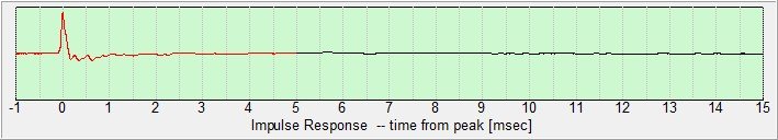
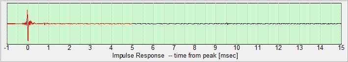
I did impulse readings for my mid and tweeter separately since i didnt like what I was seeing. For some reason the mid looks ok but the tweeter IMP looks bad. Advice appreciated. (Drivers are MW16P-8 and TW29R)
Attachments
Hi Jim,
Where were the measurements made? I ask because there doesn't appear to be any substantial reflections of the acoustic signal off walls and ceiling/floor. These reflections normally appear in an impulse response after a period of about 3mS - 5mS after the impulse when making measurements in a normal size room.
Peter
You're making a big mistake evaluating performance without XO filter on. All the data you need to know is within FR measurement which is easier to interpret than impulse response. Haven't we learned from our expert members, for instance Dr.Geddes or speakerdave, that exactly the same information is included within FR and IR?
I assume he’s asking bout the ripples and the ringing.
It sometimes makes sense to check the IR, not to trust the magnitude blindly.
The ringing could come from DAC, the ripples from early diffraction+late reflection + noise (low vol measure). Then still everything is fine.
It can also be (i have seen that) odd like this though non of the reasons above where given, but the tweeter was broken from heavy low freq sweeping. Once i had my aircon disturbing, once broken xlr-mic cable etc etc etc.
i recommend check all measure setup, clipping, SNR etc. also check DC offset in the step response.
Cheers
Josh
I dont know what brand is twr29 but if the early disruption maybe a result from the tweeter front plate?
Ok so the brand in Satori, I measured 1m away, the XO is in the circuit but I am measuring one driver at a time and I was concerned about the ringing on the tweeter resp.
Since there is pre and post ringing, you are probably seeing the anti-aliasing filter. There cannot be any pre ringing in a minimum phase measurement like a tweeter.
Hi,
At which sample frequency is your measurement system running?
I have the same pre-ringing in all my tweeter measurements with a Clio win7 system. It is running at fs=44kHz. It means you can have alias products if you measure frequencies above fs/2 = 22kHz and for a tweeter these frequencies can exist.
I don't know the exact explanation for the pre-ringing, but one should respect the sample theorema. So you should have to apply low frequency filtering for the tweeter at 20kHz, but that isn't practical.
In the Clio system I see no problem in the frequency response amplitude after applying the FFT in the case of an impulse response with pre-ringing. For the phase it is important to start the FFT window just before the impuls is starting and cancel the pre-ringing in that way.
Looking on the DaytonAudio site I don't find so directly the sample frequency fs in the OmniMic V2 information.
Anti-aliasing filters make a convolution of your signal with a sinc function (approximated): Sinc filter - Wikipedia
If your measurement gear sample rate matches that of the DAC, the ringing looks like one sample positive, then negative, then positive and so on.
Of course for crossover design, set time = 0 at the start of the peak of the impulse, after the pre-ringing.
If your measurement gear sample rate matches that of the DAC, the ringing looks like one sample positive, then negative, then positive and so on.
Do I understand you correctly that you say that you should cut off the pre-ringing? The pre-ringing actually is part of the signal, I think you should not omit it. Without adding pre-ringing, the low pass filter in the DAC cannot be linear phase. So you would add a phase shift at high frequencies if you omit it. Not too relevant for phase around the lower cutoff of a tweeter though.For the phase it is important to start the FFT window just before the impuls is starting and cancel the pre-ringing in that way.
Of course for crossover design, set time = 0 at the start of the peak of the impulse, after the pre-ringing.
Last edited:
Yes you are rigth, the amplitude is slightly affected above 10kHz, starting the FFT window just before the impulse. What you can do also, is starting the window before the pre-ringing and compensate for the delay to obtain a correct absolute phase, that is more correct for both amplitude and phase.
Most software measurement programs also have anti-aliasing filters, so it could also be there. Do a loop-back measurement and I'll bet its still there.
Omnimic samples at 48kHz.
With any converter or system that is both bandlimited (20kHz in this case) and has flat phase response (which is done by EQ and the FIR part of the chip's antialiasing), then there will necessarily be "pre-ring" (and post-ring, for that matter). Don't believe the crap in hifi magazines about pre-ring being some kind of error that needs to be fixed. It's the ONLY correct impulse response for a frequency response that both abruptly drops off and also has flat phase response -- anything ELSE (in the same bandwidth) is an error.
If we assume that we can't hear above 20kHz (which is almost certainly true for any of us old enough to be able to read this board!), then the ringing is entirely due to the LACK of frequency content in the range beyond our hearing. Put that range back (if it were possible) and the pre-ring vanishes. Roll off the band gently and the pre-ring drops out of sight (that's why your midrange IR doesn't show any). Let the phase response drop fast somewhere before the response drops (like minimum phase for that shape) and the pre-ring vanishes.
Don't believe the crap in hifi magazines ...
You mean that the hifi magazines got it wrong! How can that be! 😱
Step response could tell that easier. But you must look at frequency response too, and know the type of acoustic slopes.
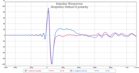
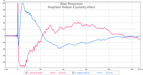
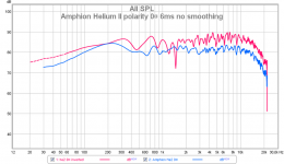
Here is my example of a 2-way speaker with asymetric xo, polarity same and woofer reversed, Amphion HeliumII. REW with UMIK-1, from different sessions, different spl and distance etc.
Here is my example of a 2-way speaker with asymetric xo, polarity same and woofer reversed, Amphion HeliumII. REW with UMIK-1, from different sessions, different spl and distance etc.
Attachments
Last edited:
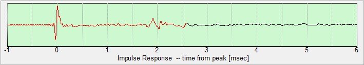
Jim, your measurement is an inverse polarity impulse response.I redid the XO to a lower order 6db LP on the MW16 and 12db on the TW29R. The impulse is cleaner but it goes negative on the leading edge. Does that mean I should reverse polarity?
With a positive polarity the impulse first has a rising edge, followed by a falling edge and after that the impulse goes to zero with a certain decay time.
Here a plot of a tweeter measured on IEC baffle, with a positive polarity.
You can also see on the phase response. For a tweeter the phase should cross the zero degree line at a few kHz. For a woofer and a midrange this crossing is below 1kHz.
Positive impulse tweeter

Amplitude and phase tweeter

- Status
- Not open for further replies.
- Home
- Loudspeakers
- Multi-Way
- Impulse response