Many times in the past I have had two diffferent amplifiiers hooked into the same pair of speakers so I could switch between them to see if I could hear any differences, and recently someone has absolutely insisted that I never did that because it would cause one of them to blow. I don't even think that would happen if they were both on at the same time, but I could be wrong... any input?
I suggest verifying this with both on at the same time could be expensive.
With similar rated amplifiers as long as one is turned off then there is no real
danger, though cable loading and possible zobel correction will be unrealistic.
As well as reverse voltage diode practise differences in the amplifiers.
Its a practise of little merit for direct comparisons.
") sreten.
sreten.
With similar rated amplifiers as long as one is turned off then there is no real
danger, though cable loading and possible zobel correction will be unrealistic.
As well as reverse voltage diode practise differences in the amplifiers.
Its a practise of little merit for direct comparisons.
sreten.For a simple class b output, that would be rather dangerous.
With the supplies off, it is possible to reverse bias the emitter-base junctions, and forward the collector-base junction.
That would mean that somewhere in the 5 to 15 volt region, you would be able to put the e-b junctions into reverse avalanch breakdown, with very little to prevent destroying the output transistors..
Do not do it for any solid state amps..
John
jneutron said:With the supplies off, it is possible to reverse bias the emitter-base junctions, and forward the collector-base junction.
That would mean that somewhere in the 5 to 15 volt region, you would be able to put the e-b junctions into reverse avalanch breakdown, with very little to prevent destroying the output transistors..
John
Can't see this happening myself,
sreten.sreten said:
Can't see this happening myself,
Hmmm...
Pop up a schematic of a simple B output stage, emitter out..
Short across the supply capacitors, to represent the off condition.
Put 20 volts positive on the output line.
You are taking the NPN emitter above the supply voltage present on the collector.
C-B junction will be forward biased, E-B junction reversed.
Typical E-B reverse breakdowns are 5 to 15 volts..
If good current is drawn at 15 volts, the base dissipation will fry the unit.
Cheers, John
Hi John,
don't really want to argue about this as we both agree its not a good idea.
Seems to me quite complicated if you include the drivers (which supply base
current so we are talking 10V to 30V for both junctions) and the driver base
resistance will limit current, which is usually ridiculousy high.
sreten.
don't really want to argue about this as we both agree its not a good idea.
Seems to me quite complicated if you include the drivers (which supply base
current so we are talking 10V to 30V for both junctions) and the driver base
resistance will limit current, which is usually ridiculousy high.
sreten.sreten said:Hi John,
don't really want to argue about this as we both agree its not a good idea.
Seems to me quite complicated if you include the drivers (which supply base
current so we are talking 10V to 30V for both junctions) and the driver base
resistance will limit current, which is usually ridiculousy high.
We appear to disagree on a point...we are not arguing. We are having a nice discussion...
I have been talking about when an amplifier is off..you have obviously been talking about the amplifier being on...a funny discontinuity of understanding...
On, I agree with you completely..
Off is what I have been talking about...where the output devices are subjected to reversed voltages..
Cheers, John
At the risk of making a fool of myself:
isn't the back direction of the typical B-E "diode" somewhat like a poor zener, at about 5 volts? Given this and the diode between B-E, there seems to be a great risk of damage if the supply is grounded and say 20 volts is applied to the output of the amplifier.
For sure, I'd recommend him to have a (non-shorting) switch or relay to flip between the amplifiers.
sreten said:No I'm talking off.
The output pairs bases are not connected to the voltage rail,
they are typically driven by the emitters of the driver pair.
This is for the most common emitter follower pair, CFP is different....
OH....you are considering what is connected to the base as protecting it...I understand now why you do not understand my point..
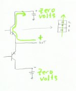
Within the transistor, if you connect a positive voltage to the emitter, neg to the collector...you will forward bias the c-b junction, reverse the e-b. There will be nothing in this path to limit current.
Here's a pic.
Cheers, John
Attachments
And what you are ignoring is what is connected to the
base of the transistor affects the ratio of the voltages.
But I think we should leave it here, the original post stated
it had been done many times, without apparent mishap.
Most sensible people wouldn't consider it for fear of
something horrible happening which is sensible.
I'm more interested in the fact its a totally
stupid way to compare amplifiers - to be blunt.
And if the earths of the the two amplifiers are common the real
issue is "catching diodes" used from each voltage rail to output.
sreten.
base of the transistor affects the ratio of the voltages.
But I think we should leave it here, the original post stated
it had been done many times, without apparent mishap.
Most sensible people wouldn't consider it for fear of
something horrible happening which is sensible.
I'm more interested in the fact its a totally
stupid way to compare amplifiers - to be blunt.
And if the earths of the the two amplifiers are common the real
issue is "catching diodes" used from each voltage rail to output.
sreten.sreten said:And what you are ignoring is what is connected to the
base of the transistor affects the ratio of the voltages.
You are correct...I am not considering it...
Can you draw up what you are talking about?
As, I do not see how anything connected to the base will prevent e-b reverse breakdown of the main outputs.. unless it shunts between e-b, like say a 100 ohm resistor, which would then start to attack the driver circuitry e-b.... Remember, it is an output stage that is trying to force the voltages there, the non active semi's won't do too much to protect themselves..
A drawing would help to explain your point..
Till tomorrow...
Cheers, John
Either way I did this by mistake, good thing that it was a crappy chip amp from a set of computer speakers.
I had the chip amp connected to some speakers and I hooked up my other amp forgetting to disconnect the other one. Played music sounded good, noticed the LED power on for the chip amp was lighting up in time to the bass drum thumping. ONE DEAD CHIP AMP lol.
I had the chip amp connected to some speakers and I hooked up my other amp forgetting to disconnect the other one. Played music sounded good, noticed the LED power on for the chip amp was lighting up in time to the bass drum thumping. ONE DEAD CHIP AMP lol.
5th element said:Either way I did this by mistake, good thing that it was a crappy chip amp from a set of computer speakers.
I had the chip amp connected to some speakers and I hooked up my other amp forgetting to disconnect the other one. Played music sounded good, noticed the LED power on for the chip amp was lighting up in time to the bass drum thumping. ONE DEAD CHIP AMP lol.
Don't those chip amps have the neg supply rail as the substrate of the IC?
And, all of the xistors on those chips are isolated from the silicon substrate by reverse biased pn junctions..
So any attempt to bring inputs, or outputs, or anything to a voltage level more negative than the backside will result in heartache...
Cheers, John
I am the original thread starter.... why is it a totally stupid way to compare amplifiers? I never had a single problem, but it is important to note that the amplifiers were never outputting anything at the same time, one was always off while the other was on. I think it is an EXCELLENT was to test amplifiiers that are of similar output levels because: A: The instant transition is the only real way to hear any difference, because if there IS any difference, I believe it would be so slight that you would forget it while you were in amplifier transition and both amps were off and you were hearing nothing for 3 minutes, if you did it the slow way. B: I don't think there is ever a real difference anyway, unless you are talking about tubes vs. solid.
My humble opinion of course. I just think amplifier sound quality diffferences are WAAAAAAAY overrated. Not that that is the point here.
My humble opinion of course. I just think amplifier sound quality diffferences are WAAAAAAAY overrated. Not that that is the point here.
I agree with you that it is very valueable to compare amplifiers, and that making quick flipping between the two is a way to make the comparisons more easy and this in turn makes the test better.
I also think that the differences between amplifiers are small and exaggerated.
My concerns about the test method are two:
1. I would not dare to take the risk to blow the inactive amplifier with the power from the other. Your experience tells me the contrary, so I may be wrong here.
2. If you accidentally happen to have the power on on both amplifiers, the risk would be even greater, unless the outputs have protection circuitry.
3. The load of the incative amplifier is almost certainly non-linear. While this wether be a test if the amplifier can drive a non-linear load or not, it is hardly a fair way to compare two amplifiers. The one with the most non-linear power-off impedance would win.
Was that three?
As I said, I'd set up this test using a switch or a relay to switch between the amplifiers. Point 3 above would be reason enough for me to do that. Points 1 & 2 would convince me even more.
The Paulinator said:I think it is an EXCELLENT was to test amplifiiers that are of similar output levels .......
My humble opinion of course. I just think amplifier sound quality diffferences are WAAAAAAAY overrated. Not that that is the point here.
Simply put its not remotely excellent.
sreten.I think the moethod is certainly excellent compared to what people usually do, although it sounds like it might not be the safest way to do it. I think my assumption when I did this (being a person who does not have a great understanding of how electricity would act in this case) was that the power would ina sense be drawn to the speaker, and would never even get to the amplifier, almost like the speaker was a ground compared to the output of the amp and the electricity would just prefer to go there, but again, that was my thought process and nothing negative happened when I tried it so I thought I was right. My bad.
- Status
- This old topic is closed. If you want to reopen this topic, contact a moderator using the "Report Post" button.
- Home
- Loudspeakers
- Multi-Way
- Does having two amplifiers hooked into the same pair of speakers cause any problems?