Obviously the following all depends on crossover order and bsc etc.
So I expect this to be a fairly generalised question and answer.
In bass low pass crossovers you have a series inductor with a shunt capacitor.
For BSC either a second series inductor after the shunt cap, or a larger value inductor.
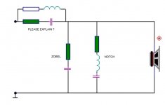
I have been seeing more designs where there is a (series) capacitor/resistor across the (single series) inductor.
Q1. For BSC what are the pro's / con's of two inductors vs a single larger one ?
Q2. What are the pro's / con's of the version with a cap/resistor across the inductor ?
Thanks")
So I expect this to be a fairly generalised question and answer.
In bass low pass crossovers you have a series inductor with a shunt capacitor.
For BSC either a second series inductor after the shunt cap, or a larger value inductor.
I have been seeing more designs where there is a (series) capacitor/resistor across the (single series) inductor.
Q1. For BSC what are the pro's / con's of two inductors vs a single larger one ?
Q2. What are the pro's / con's of the version with a cap/resistor across the inductor ?
Thanks
2 inductors in series will usually have too much resistance and raise the Q of the system, if not, no problem. Resistance of the inductor shouldn't exceed 10% of the impedance of your woofer.
When you see a cap in series with a resistor across a woofer, it is called a zobel. Impedance rises with frequency, in a woofer' s voice coil, the zobel flattens the impedance so the inductor sees a steady impedance.
Sent from my ASUS MeMO Pad 7 using Tapatalk
When you see a cap in series with a resistor across a woofer, it is called a zobel. Impedance rises with frequency, in a woofer' s voice coil, the zobel flattens the impedance so the inductor sees a steady impedance.
Sent from my ASUS MeMO Pad 7 using Tapatalk
IMHO, the one with the least parts wins. So, if possible this is the 2nd order filter, with adjustments made mostly in the coil for BSC. Sometimes picking a slightly smaller wire gauge can also help. My LM-1 depends on this a little.
There is also the matter of resistor power and wasted heat. Coils usually have really high power ratings (like 200W or more) so they are a better place to waste power than in a resistor. I'm also under the impression, though I have not really done a direct comparison, that using the low pass filter for BSC you will waste less power/heat overall. I could be bonkers with this one.
Adding a second inductor is not BSC, but adds a filter pole. That is, you go from 2nd order to 3rd order.
It may help if someone can offer you an XSim file you can play with and try alternatives with.
Best,
E
Last edited:
2 inductors in series will usually have too much resistance and raise the Q of the system, if not, no problem. Resistance of the inductor shouldn't exceed 10% of the impedance of your woofer.
When you see a cap in series with a resistor across a woofer, it is called a zobel. Impedance rises with frequency, in a woofer' s voice coil, the zobel flattens the impedance so the inductor sees a steady impedance.
Sent from my ASUS MeMO Pad 7 using Tapatalk
Total coil resistance isnt an issue in this case.
8 ohm driver, total inductor dcr of 0.3 ohms.
Yes No I know about zobels.
I'm referring to the series inductor having a cap and resistor in parallel with it.
IMHO, the one with the least parts wins. So, if possible this is the 2nd order filter, with adjustments made mostly in the coil for BSC. Sometimes picking a slightly smaller wire gauge can also help. My LM-1 depends on this a little.
There is also the matter of resistor power and wasted heat. Coils usually have really high power ratings (like 200W or more) so they are a better place to waste power than in a resistor. I'm also under the impression, though I have not really done a direct comparison, that using the low pass filter for BSC you will waste less power/heat overall. I could be bonkers with this one.
Adding a second inductor is not BSC, but adds a filter pole. That is, you go from 2nd order to 3rd order.
It may help if someone can offer you an XSim file you can play with and try alternatives with.
Best,
E
ok so if the xover is 1500 and the bsc is 600, how does one tune the step that will be between these two points ?
Because don't the two need different roll offs ?
Att image is not what I'm working on, just a random web example to help me express my question.
EDIT.
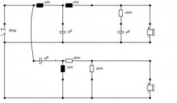
Second image att is the actual xover I have at present (values wiped for possible comercail reasons
)So what im looking at is, what if any possible improvements (or otherwise) would I get from changing the low pass section to that of the first image with the cap / resistor across the coil.
Attachments
Last edited:
Referring to the image, the "please explain" RC is a notch not used for BSC. It is used for example to tame the breakup of a woofer, see here: SEAS 5INCH (look down in the page for the W15CY001 crossover, there is a graph of the transfer function and a FR with and without RC)
The other kind of notch can be used for taming the bump related to the baffle step, also shown in the same example. Here is also an explanation about it: SEAS CURV
Ralf
The other kind of notch can be used for taming the bump related to the baffle step, also shown in the same example. Here is also an explanation about it: SEAS CURV
Ralf
EDIT.
Second image att is the actual xover I have at present (values wiped for possible comercail reasons
And how much exactly will be our cut for teaching you how to do XO filters? A magnifying glass wouldn't be enough to see that. Ha Ha Ha.

Hi, purely for the joy of throwing a spanner in the works...... Baffle Step Compensation
And how much exactly will be our cut for teaching you how to do XO filters? A magnifying glass wouldn't be enough to see that. Ha Ha Ha.
HA, you base your comment on the idea that I might actually get some sort of financial reward.
I hope I do, but the reality may be different
Actually I do have the crossover in and running.
Have had for a while.
And to be honest (to me) it sounds pretty good.
Measures within 2db across the bulk of the spectrum.
But I always wonder if I can't do better.
And lets face it, passive xovers always seem to be an area where everyone seems to always be learning..
Hi, purely for the joy of throwing a spanner in the works...... Baffle Step Compensation
I shan't complain as I like throwing spanners myself
- Status
- This old topic is closed. If you want to reopen this topic, contact a moderator using the "Report Post" button.
- Home
- Loudspeakers
- Multi-Way
- Low pass crossover design questions.