Are 1st Order Crossovers 0 degrees or 90 degrees out of phase?
I know 2nd order is 180, 3rd order is 270 and 4th order is 360 (effectively 0). So it makes sense that 1st order (and probably 5th order) are 90.
Please don't tell me to google this, I can find several websites for either answer.
I know 2nd order is 180, 3rd order is 270 and 4th order is 360 (effectively 0). So it makes sense that 1st order (and probably 5th order) are 90.
Please don't tell me to google this, I can find several websites for either answer.
Bv, it's 90 degrees per pole. So, 1st order = goes from zero to 90 degrees. However, acoustic distances also matter, so phase alone isn't enough to determine additive and destructive interference. ")
Also, remember that phase goes in one direction for LP, the other for HP. I forgot which is which, but be consistent. That is, a 1st order HP and 1st order LP will be UP TO 90 degrees out of phase with the original, BUT 180 from each other. So assuming no acoustic offset, they would cancel each other out perfectly.
Grab the XSim crossover simulator and play with this with "ideal" drivers. You'll get a much better understanding if you can play with crossovers and do this in real time.
XSim free crossover designer - diyAudio
Best,
Erik
Also, remember that phase goes in one direction for LP, the other for HP. I forgot which is which, but be consistent. That is, a 1st order HP and 1st order LP will be UP TO 90 degrees out of phase with the original, BUT 180 from each other.
So assuming no acoustic offset, they would cancel each other out perfectly. Grab the XSim crossover simulator and play with this with "ideal" drivers. You'll get a much better understanding if you can play with crossovers and do this in real time.
XSim free crossover designer - diyAudio
Best,
Erik
Last edited:
BTW, it really matters less than it would seem to, because the physical position of each driver adds delay (which is frequency-dependent phase shift, by definition). Also because each driver will ALREADY have several poles of highpass and lowpass characteristic on their own, acoustically. The "first order" crossover thing is only for the electrical passive components' part of the overall response, and is more or less just a marketing thing. You can get to something that acts as if first-order overall, but only by controlling the positioning (or delay by other means, i.e., DSP), by playing with crossover EQ, and certainly not without actually measuring what is going on. Doing a passive "first order" crossover will give you little more than some savings in components cost.
Assuming the drivers were each ideally flat in response, equidistant from the listener, and a first order filter is the only thing acting on that...
Phase will be 90 degrees apart. Response will be -3dB on the individual drivers at the crossover. Overall, both response (listening position) and power will be flat, although the response will lobe such that it is +3dB off axis.
Phase will be 90 degrees apart. Response will be -3dB on the individual drivers at the crossover. Overall, both response (listening position) and power will be flat, although the response will lobe such that it is +3dB off axis.
If by that you mean it is hard to achieve in practice but yet people still like to hear it said?...The "first order" crossover thing is only for the electrical passive components' part of the overall response, and is more or less just a marketing thing.
Last edited:
This is why I mentioned ideally flat drivers, so their response could be linked to their input.I meant this question to be about the electrical components only. Obviously different drivers will do different things.
Bv, it's 90 degrees per pole. So, 1st order = goes from zero to 90 degrees....
...Also, remember that phase goes in one direction for LP, the other for HP. I forgot which is which, but be consistent. That is, a 1st order HP and 1st order LP will be UP TO 90 degrees out of phase with the original, BUT 180 from each other.
Best,
Erik
You mixed up some things.Also, remember that phase goes in one direction for LP, the other for HP. I forgot which is which, but be consistent. That is, a 1st order HP and 1st order LP will be UP TO 90 degrees out of phase with the original, BUT 180 from each other.
1st order HP and LP transfer functions are always 90deg apart from each other, at any frequency. Which also means phase must go into the same direction (increasing at low frequencies).
90deg phase offset adds in quadrature, each transfer function is 3dB (factor of sqrt(0.5)) down at XO freq. Polarity doesn't matter for summed amplitude (a feature of any quadrature type crossover) but for phase it matters a lot: with one of the functions inverted you get 180deg total phase rotation (2nd order allpass behavior), not exactly what one would want...
Last edited:
The phase angle is related to the rate of change of the amplitude. The amplitude plot does not snap immediately from 0db/octave to 6 dB/octave therefore the phase angle does not go from 0 to +-90 degrees with no intervening values.
Since the slope transitions gradually through "knee" so does the phase angle.
Since the slope transitions gradually through "knee" so does the phase angle.
KSTR, you said the phase was always 90 degrees at any frequency and that's not true so I was trying to clarify my statement about phase goes UP TO 90 degrees in a circuit with a 1st order filter.
The rest of your typing, which made little sense to my eyes, didn't seem to apply to anything I had said. If it did it's such a miscommunication that I'm too tired to try to asnwer.
The rest of your typing, which made little sense to my eyes, didn't seem to apply to anything I had said. If it did it's such a miscommunication that I'm too tired to try to asnwer.
Last edited:
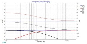
Ahhh, sorry, I misread. Here's a plot of a high and low pass filter doing just that:

Of course, as pointed out, for speakers this relationship is kind of irrelevant as it doesn't include driver and distance contributions, and in the end the actual crossover points may not be electrically symmetrical.
The top 3 lines are phase, the bottom three amplitude.
The blue line is the combined result in both groups.
Attachments
Last edited:
Where they meet at the -3dB point the phase is +45deg and -45deg. (The real and imaginary parts are equal.)
Phase always falls with frequency using passive components.
Cap stop DC so no real part gets through. Hence all imaginary and +90 degrees phase.
Cap let all high frequency through so no imaginary part. Hence all real and 0 degrees phase.
Coil let all DC through so all real and 0 degrees phase.
Coil stops all high frequency so no real part and -90 degrees phase
...Of course, as pointed out, for speakers this relationship is kind of irrelevant as it doesn't include driver and distance contributions, and in the end the actual crossover points may not be electrically symmetrical...
It gets worse than that in the measuring of capacitors. The notion that a HP filter moves the acoustic center of it's driver forward is a conundrum of it's own. This implies that current comes out of a capacitor ahead of the voltage that created it. This would mean that capacitors are acausal, which we know they are not. Nothing comes out before something goes in.
The current leading voltage as measured in steady state sinewave testing does not hold up under impulse or single sine measurement, so, which side of this leading lagging thing are we really on?
Barry.
- Status
- This old topic is closed. If you want to reopen this topic, contact a moderator using the "Report Post" button.
- Home
- Loudspeakers
- Multi-Way
- 1st Order Crossover Phase Shift