Could someone please post a drawing or diagram of the point of interaction at 1/4 wavelength.synergy style horn
In an 60 x 60 horn or 90 x 60 horn at 800hz for example.
Is it the 90* right angle point between the two sources or the path along the inside of the horn driver to driver.
Hope this makes sense
800hz _43cm. 1/4 = 10.75cm
Does delay with minidsp change anything overall?
In an 60 x 60 horn or 90 x 60 horn at 800hz for example.
Is it the 90* right angle point between the two sources or the path along the inside of the horn driver to driver.
Hope this makes sense
800hz _43cm. 1/4 = 10.75cm
Does delay with minidsp change anything overall?
The straightest path is from driver to driver. Some will take a longer path. (The sound may be assumed to form some kind of wavefront, but really it's just operating into an acoustically small space where it is not critical.)the path along the inside of the horn driver to driver.
The point of the synergy is that it adjusts the acoustic centers such that you can get nice in-phase summing and makes it possible to get flat phase.
When you have a high pass crossover (for a tweeter), it will move the acoustic center of the driver forward. A low pass crossover moves the acoustic center backward. On a flat baffle, if you have a tweeter and woofer, it will result in phase change through the crossover (we're simplifying here; in a real design, there are many factors affecting the combined phase).
You must have seen Troel's designs where he moves the woofer forward in order to get better time alignment with the tweeter. A sloped baffle does the same thing. A synergy is just taking this concept to the extreme. It combines the woofer and tweeter in space such that they can add nicely and the whole thing feels like it is coming from the same point, and you get directivity control. It is quite neat actually.
Delay in miniDSP would probably help as it may not be possible to get your slots precisely where they want to be given the physical dimensions of the horn, drivers, etc.
The straightest path is from driver to driver. Some will take a longer path. (The sound may be assumed to form some kind of wavefront, but really it's just operating into an acoustically small space where it is not critical.)
that may well be but when I designed, built, and measured a Synergy horn, the reflection null was consistent with the path length being calculated along the horn axis. Apparently the acoustic summation to form a null occurs on axis, equidistant from the surrounding mid drivers. This may be different for Bill's latest creation that only has a single mid.
I calculated a path length of 10 cm based on an acoustic path length of 6.5 cm for a BMS4550 and the measured null was consistent with a path of 8.9 cm. The original L12 from the BWaslo spreadsheet was 5.72 cm. Its a 90 degree horn so the distance along the wall is 8.09 cm. To that you need to add the thickness of the CD mounting plate and the CD's internal acoustic path length.
Yes, a long path inside the CD really does pull down the reflection null frequency but those big CDs ought to be able to support a low crossover frequency.
But it is narrow down there. Have you considered trying the hornresp multiple entry horn sim?
I am using an iPad mini at present, my laptop has just had a new hard drive fitted and operating system installed it needs a new keyboard, minidsp reinstalling,REW, other software so out of action for a while.
Hornresp seems daunting and I keep seeing requests for help regards for synergy designs,last thing I want to do is clog the forum with help requests on using it
")
Regards difference in angles the horn can be 90x60 or 60x60 approx 24" wide mouth which ever patterned is better.
I want to only use one mid 12" jbl 2206h and build a box under the horn but ported into the horn bass reflex
I can work out the 2 cubic ft part out easily enough port size is on jbl website
Tuned frequency 40hz
So a horn with a 12" driver on the lower panel which then forms the 2 foot chamber ported back up into the latter part of the horn mouth
It's got to be done
Last edited:
Hi Charlie:
I hate those days lost due to computer/OS upgrade!
HornResp will yield to a concerted effort; start with those simple online tutorials and, with the help of BWaslo's spreadsheet you can graduate quickly to an offset bandpass mid and then a Synergy.
I've just built a 90x45 horn and observed that the radiation doesn't fill the horizontal pattern as uniformly as I expected. Both waistbanding and lobing occur which don't matter quite as much if you listen on axis. 90 degree wide horns are more difficult for a number of reasons. Unless you need the wide coverage, you would be better off with a 60x60 horn; especially since those CD's of yours are not 1" exit diameter and will already tend to beam at HF.
A single 12" mid/woofer can be suffiicient if you can get it to play high enough. Two things happen with a large diameter driver ported through a horn wall. First, the air trapped between the cone and the horn wall has a low pass filtering effect so you may need a "volume plug" to reduce it. Second, sound arriving at a port hole from the far edge of the cone can be out of phase with sound arriving from near portions of the cone, causing cancellation. This latter effect starts to be a problem with 6" and 8" drivers for a 1 Khz XO. Your 2445 crossing at 500 Hz has much greater chance of success than the 2426 crossing at 800 Hz.
The original question was implying there may be a difference at different angles and hence the behaviour of the apex, despite its length, once it becomes acoustically narrow. Even before this consideration there will be a partial reflection as the throat goes narrow.
OK, you've got me thinking about this.
Its a given that the multipile mids (and CD) combine to form a point source. I infer from this that the acoustic center within the range covered by the mids is at a point equidistant from the mids. For Synergies with mids located symmetrically about the axis, this point will be on the axis. Its from this point that pressure waves spread forward and backward in the horn. Thus when estimating the reflection null frequency, measure along the horn axis.
The fact that the horn is acoustically narrow at the mid entry point also supports formation of a point source. That is another way of expressing the constraint that the mid entry points must be within 1/4 lambda of each other at XO or that the circumference of the horn there be less than lambda at XO.
For the rearward radiation, the narrowing horn forms a funnel which concentrates the sound towards the apex. Partial reflections, if any, are still net rearward and have a concentrative effect; let's not speculate about rearward HOMs.
I think the primary effect of different angles is in the expansion rate of the horn. The wider the horn, the more quickly it expands and thus the more difficult it is to get the mid entry points within 1/4 lambda of each other at XO and the circumference of the horn there to be less than lambda at XO.
OK, you've got me thinking about this.
Its a given that the multipile mids (and CD) combine to form a point source. I infer from this that the acoustic center within the range covered by the mids is at a point equidistant from the mids. For Synergies with mids located symmetrically about the axis, this point will be on the axis. Its from this point that pressure waves spread forward and backward in the horn. Thus when estimating the reflection null frequency, measure along the horn axis.
XO.
OTOH, Charlie is planning a single mid so it seems he should measure along the horn wall. Assuming that the driver is butted up against the CD mounting plate and that the port holes are constrained to be in the corners of the horn, that distance will be longer for a 90 degree wide horn than a 60 degree wide horn.
Having spent the last couple of hours dissecting danleys patent and diagram/graph of the sh50 I am going with that shape so 20"x20" mouth 20" inches deep my protracter gives 53/55 degree.
What makes it a bit easier is the distance from the (2d triangle drawing) throat is equal to the distance in height expansion this can then be times x4 for square inch area
By my understanding the patent danley quotes xover 1000hz at 10"square that been 3.16" from the throat and 3.16" at the side
1000hz 1/4 wavelenth 3.68
So 800hz. 1/4 = 4.11"
Last edited:
Hi Charlie:
I've got reservations about what you are trying to do but I did this sketch to see what it looks like anyway. OTOH, a couple of those 4" closed back Celestion mids and a more complicated XO might be all it takes to make it work well.
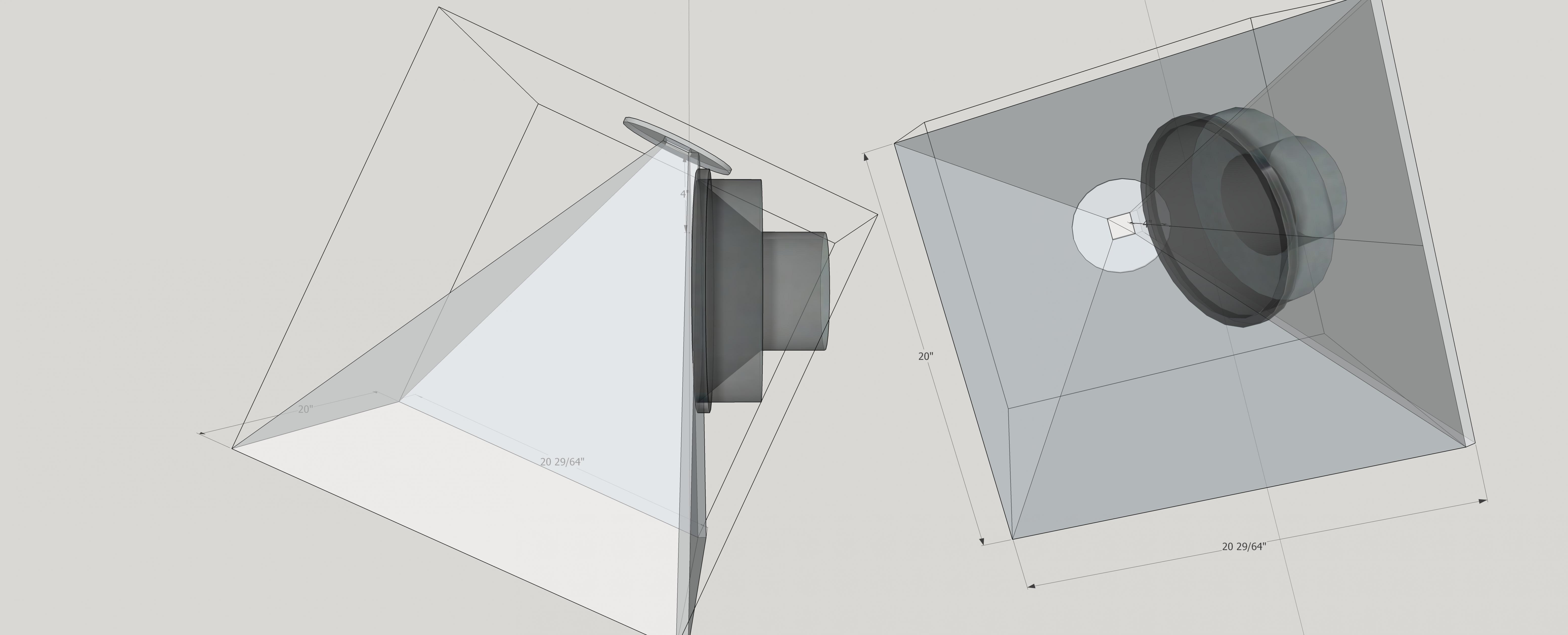
You can squeeze the woofer in close enough but port holes close enough to support the 40 Hz tune you are looking for are likely to compromise your HF. Don't forget you need to take into account the acoustic path inside the CD.
Sketchup file attached....
Jack
I've got reservations about what you are trying to do but I did this sketch to see what it looks like anyway. OTOH, a couple of those 4" closed back Celestion mids and a more complicated XO might be all it takes to make it work well.
You can squeeze the woofer in close enough but port holes close enough to support the 40 Hz tune you are looking for are likely to compromise your HF. Don't forget you need to take into account the acoustic path inside the CD.
Sketchup file attached....
Jack
Attachments
Thanks Jack appreciate the time it took to model so far
If you could put a 2 cubic foot box around the mid bass driver using the horn width mouth is what I am aiming for.plus material thickness
And 2 reflex ports vent area square inches 12.6" length 7.6"
500x500 x500 mm(50x50x50 cm) These are the final internal horn measurements
I work in millimeters/cm easier to transgress wavelenth measurements
Yes, the sound will be equally spaced around the horn axis, and would remain so in an axisymmetrical guide but individual components won't necessarily travel axially. As you say, the range is limited. A point source (which implies a cone based waveguide) can be achieved if the wavefront has an effective focal point that coincides with that of the waveguide's conical asymptote.. In this case it is being taken care of only by the acoustically small space.Its a given that the multipile mids (and CD) combine to form a point source. I infer from this that the acoustic center within the range covered by the mids is at a point equidistant from the mids. For Synergies with mids located symmetrically about the axis, this point will be on the axis.
Witout this constraint, reflection at the smaller throat wouldn't necessarily align to create a complete cancellation notch, though the reflection may amount to a point source.
It was really only 15 minutes or so, for a quick sketch using a driver model I already had. Exponentially more time would be needed for real drawings.
If you build a 20" ID cube and put the horn inside it, the horn will occupy about half of the volume, leaving just over 2 cu.ft. for the driver and vent. You should probably make it a few inches taller to allow for the vents coming out the bottom and a few inches deeper so the CD can be inside it. It won't be all that big. You could easily have quite a bit more volume and get by with a shorter vent, which might not be a bad idea if you are using the mid up to 800 hz.
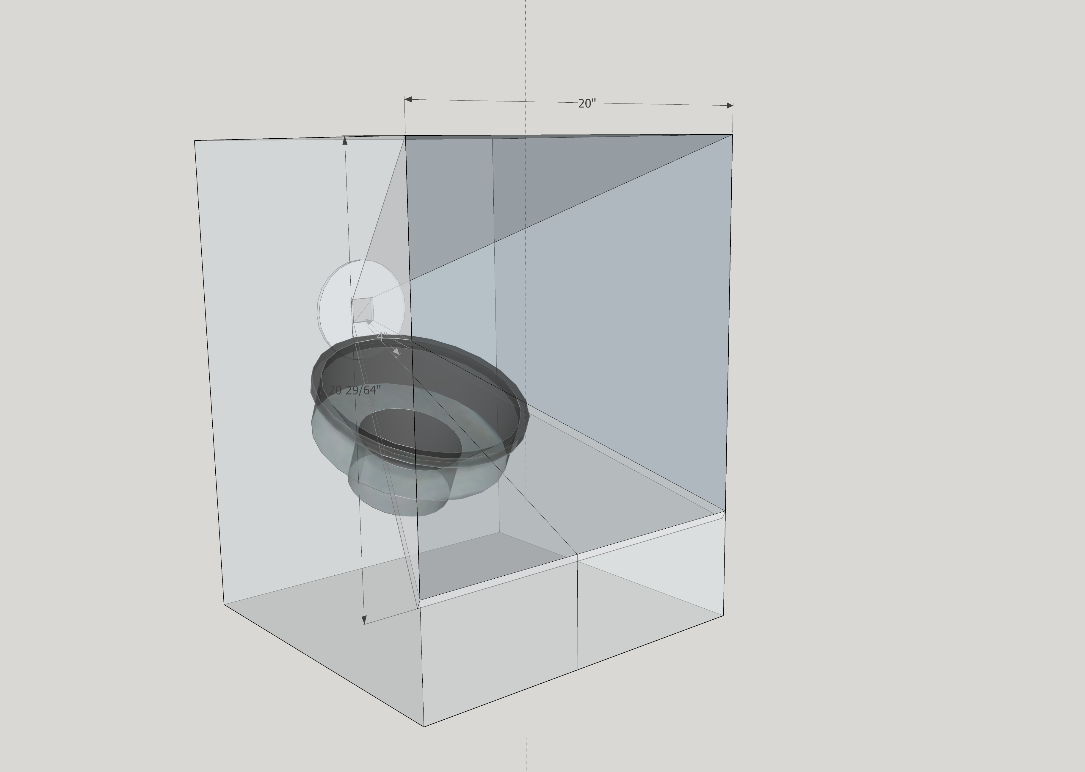
If you build a 20" ID cube and put the horn inside it, the horn will occupy about half of the volume, leaving just over 2 cu.ft. for the driver and vent. You should probably make it a few inches taller to allow for the vents coming out the bottom and a few inches deeper so the CD can be inside it. It won't be all that big. You could easily have quite a bit more volume and get by with a shorter vent, which might not be a bad idea if you are using the mid up to 800 hz.
Attachments
Wow what software are you using to draw this?
If I can pull this design off it will be simple for other DIYers to follow less angles and trigonometry to worry about, the basics are in the initial horn build where everyone struggles myself included.
But I happened on a free online calculator for the horn.
So it's just a case of mounting the horn ( top three segments) and the lower segment of the horn, which then forms the top of the under enclosure of a suitable driver
So the last drawing you made needs the side panels removing so that the mid/bass drivers enclosure is totally under the horn.
Hope this makes sense
I am in the process of building a prototype 200x200x200 horn for simplicity
I had thought about putting the reflex ports in the front face for ease, but if in the horn it is still in synergy
By not using the back space behind the horn it is easier for others to replicate
Those that can easily replicate the dimensions behind the horn will be limited to the drivers available frequency port tuning
Cheers
Last edited:
- Status
- This old topic is closed. If you want to reopen this topic, contact a moderator using the "Report Post" button.
- Home
- Loudspeakers
- Multi-Way
- Quarter wavelength point of interaction synergy horn