Hi, im fairly new to this forum, ive picked up alot of very useful info in my time browsing.
Though this forum and my experiments with Unity horns i found the VTC paraline box, id like to try and design something similar with my own design HF system. So basically im looking for some help simming the 8" drivers in a VTC Paraline style box in HornResp.
Ive tryed a few different ways but im not 100% sure im getting it right, they have all come up with roughtly the same power response between 100hz and 1khz with a slight dip at 400hz but id like to know for sure how to model the box so i can get the rear chamber correct and also if porting would aid the lower extension and what size tap/port i need going from the front of the driver to the horn?
I can post up measurements and dimensions if anyone is willing to teach me the correct way.
Thanks in advance.
Tom
Have you read the Squarepegs thread? Lots of good info in there.
My experience with the Paraline is that it's full of diffraction and the model shows a ragged response and the measurements agree with a ragged response. Not the best SQ in my opinion. You are better off trying something else along the synergy line or even using a Full range cone in a horn with bass injection ports.
If you want to model the whole Paraline with simultaneous mid or bass injection ports you can use Akabak - which allows a more accurate model.
There are models shown in Squarepegs thread.
Last edited:
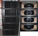
They can be modeled as an offset "Par" or "Con" horn, with or without bass reflex.Sorry maybe i explained myself wrong, im not looking to model the paraline lens/layed combiner or whatever you want to call it. Im looking at modeling the 2 x 8" section?
The tap is S2, distance of S2 to the horn apex is L1-2.Thanks, how do i tell hornresp the position of the tap in relation to the horn mouth and throat?
The "Help" file has this information. Play with the Wizard, you can see the diagram change as you move the sliders around.


Your picture shows two 8", your sim is using four drivers (2Px2S).Someone please tell me my sims are right and im on the right track?
Your sim is using 2 Pi (half space) but a line array should be elevated in to whole space (4 Pi).
Although you indicate a slight vertical expansion in the pictures, the top and bottom walls are close to parallel, so "Par" rather than "Con" is more appropriate to the horn flare depicted.
The BMS 4550 has very limited output in the crossover region (around 800 Hz is all you can expect from the 8") so you should be designing for 2 HF drivers (like VTC) or a 3" diaphragm driver (as I used in my smaller Paraline line array cabinets using 2x8").
Art
Attachments
Hi thanks for the reply ")
So ill adjust the input to be in 4Pi, with 2 drivers in series to represent the 2 drivers on the same horn in one cabinet? Then would i use the multiple speakers feature under the power response page to give an indication of multiple cabinets?
Thanks
So ill adjust the input to be in 4Pi, with 2 drivers in series to represent the 2 drivers on the same horn in one cabinet? Then would i use the multiple speakers feature under the power response page to give an indication of multiple cabinets?
Thanks
Yes, 2 drivers in series represent 2 drivers on the same horn in one cabinet.Hi thanks for the reply
So ill adjust the input to be in 4Pi, with 2 drivers in series to represent the 2 drivers on the same horn in one cabinet? Then would i use the multiple speakers feature under the power response page to give an indication of multiple cabinets?
Thanks
The "multiple speakers" feature will give an indication of the LF output potential (don't exceed Xmax, the results above Xmax are not reliable, and would be quite distorted) but are not indicative of the upper response when in a vertical array.
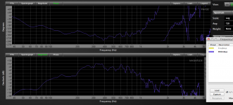
My Paraline line array uses 8" Eminence Alpha 8" speakers, individually the response rises towards the high end, in multiples the response flattens out acoustically. The response below is of a single 2x8" cabinet, free space, at 1.5 Hz resolution.
Using fourteen 8" per side (4x8" in one cabinet equal in size to a pair of the 2x8"/EVDH1AMT Paraline, but using no HF devices) requires results in a near flat response 100 Hz to 800 Hz, only requiring a .73 Q 2.5 dB boost at 355 Hz, about 17 dB LF increase compared to a single.
Art
Attachments
Last edited:
- Status
- This old topic is closed. If you want to reopen this topic, contact a moderator using the "Report Post" button.
- Home
- Loudspeakers
- Multi-Way
- Paraline horn box help needed