Hi folks,
I picked up a set of old 2-ways from the 80s (Sound Dynamics Concert Monitor 500s). Surprise, surprise... turns out one of the tweeters doesn't work and I can't source an exact replacement. I'm wondering how I can determine at what frequencies the crossover does its job so I begin sourcing replacements that would use similar specs.
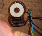
I don't own a tone generator to test what frequencies are coming off the line. I was hoping there was a way to reverse-engineer the crossover just by looking at the parts. The xover looks simple enough. There's an induction coil and 2 electrolytic caps. After the coil the tweeter's positive wire is fed by a 4.7uF cap while the 10" driver is fed by a 3.3uF cap.
Where do I start?
Thanks in advance!
I picked up a set of old 2-ways from the 80s (Sound Dynamics Concert Monitor 500s). Surprise, surprise... turns out one of the tweeters doesn't work and I can't source an exact replacement. I'm wondering how I can determine at what frequencies the crossover does its job so I begin sourcing replacements that would use similar specs.
I don't own a tone generator to test what frequencies are coming off the line. I was hoping there was a way to reverse-engineer the crossover just by looking at the parts. The xover looks simple enough. There's an induction coil and 2 electrolytic caps. After the coil the tweeter's positive wire is fed by a 4.7uF cap while the 10" driver is fed by a 3.3uF cap.
An externally hosted image should be here but it was not working when we last tested it.
Where do I start?
Thanks in advance!
Can you measure the coil inductance? If not you can unwind the wire and count the number of turns. Using inductor design calculations will give the inductance. The cap values are marked.
Air Core Inductor Coil Inductance Calculator
Air Core Inductor Coil Inductance Calculator
Sadly it's not that easy, if you can't get the same drivers then identical crossover components will not yield the same frequency response.
I suggest you buy / borrow a USB measurement microphone, then measure and simulate a crossover. It's a bit more complicated of course but then you won't have to worry about building a sub par crossover or wasting lots of money on testing different components that didn't work that well. That in addition to that it is very hard to determine what is wrong with the crossover without measuring. It is likely easier for an experienced builder but even they mostly rely on measurements.
I suggest you buy / borrow a USB measurement microphone, then measure and simulate a crossover. It's a bit more complicated of course but then you won't have to worry about building a sub par crossover or wasting lots of money on testing different components that didn't work that well. That in addition to that it is very hard to determine what is wrong with the crossover without measuring. It is likely easier for an experienced builder but even they mostly rely on measurements.
Lets keep it simple. Take a multi meter and set it to ohms. Put one meter probe on each tab on the tweeter in question. You should see a measurement around 4 to 8 ohms. No measurement usually means the tweeter is toast. If it does measure, replace the cap to the tweeter with a same value unit. I would make it a film cap. Using the ohm function, you can measure the wires coming into the cap and out to the tweeter to see if there is passing the signal.
Thanks for the suggestions. I really appreciate the time each of you took to post.
I would be stuck unwinding the coil. I don't have equipment for measuring this. I probably won't do that, given what OllBoll has said.
Indeed. I may have bitten off more than I can chew.
I don't get a reading across the two posts of the dead tweeter. (Other one is fine, mind you.) I'm going to try to remove the baffle the see if a connection got loose on the inside.
Can you measure the coil inductance? If not you can unwind the wire and count the number of turns. Using inductor design calculations will give the inductance. The cap values are marked.
I would be stuck unwinding the coil. I don't have equipment for measuring this. I probably won't do that, given what OllBoll has said.
Sadly it's not that easy, if you can't get the same drivers then identical crossover components will not yield the same frequency response.
I suggest you buy / borrow a USB measurement microphone, then measure and simulate a crossover. It's a bit more complicated of course but then you won't have to worry about building a sub par crossover or wasting lots of money on testing different components that didn't work that well. That in addition to that it is very hard to determine what is wrong with the crossover without measuring. It is likely easier for an experienced builder but even they mostly rely on measurements.
Indeed. I may have bitten off more than I can chew.
Lets keep it simple. Take a multi meter and set it to ohms. Put one meter probe on each tab on the tweeter in question. You should see a measurement around 4 to 8 ohms. No measurement usually means the tweeter is toast. If it does measure, replace the cap to the tweeter with a same value unit. I would make it a film cap. Using the ohm function, you can measure the wires coming into the cap and out to the tweeter to see if there is passing the signal.
I don't get a reading across the two posts of the dead tweeter. (Other one is fine, mind you.) I'm going to try to remove the baffle the see if a connection got loose on the inside.
No resistance means open circuit, tweeter is toast. The open tweeter coil was caused by melting the voice coil wire due to too much current, usually from playing too loud, especially with an amp that is clipping. The tweeter is dead. You'll need to replace both tweeters.
The woofers are 10" foam surround and will need to be refoamed at some point. I would recommend you let it be what it is and try to find some cheap tweeters close to the originals in impedance curve and sensitivity, if possible. Use the existing crossovers and tweek the levels with resistors if necessary and enjoy. If you want a better speaker with quality parts, I recommend you start from scratch and try a well engineered kit like Kairos or Eton S7, etc. It's guaranteed success at a good price.
If you really want to restore them, have a pro refoam the woofs, then look for a parts donor pair, or simmilar model that used the same tweeters. Maybe Athena can tell you what other models shared that tweeter.
Your photo shows a 3rd order electrical high pass filter with bipolar electrolytic capacitors and air core inductor of very small gage wire.
Are they horn tweeters like other Sound Design tweeters I see on Ebay? Can you post pic of tweeter front and rear? Sound Dynamics is now Athena Technologies. Maybe someone there can give you a hint about replacement tweeters, long shot...
I carefully refoamed the woofers already. From the one speaker that is whole, I'm not convinced it is really of a quality that makes it worth restoring. But this is as much about learning as anything.
Someone has kindly offered to donate an original tweeter from another otherwise defunct set. I'll make use of it, and hopefully all will be well.
As a side note, I have ordered some replacement caps. We'll see if that improves the performance. The caps are out a bit. The 4.7uF caps sit at about 4.9uF and the 3.3uF caps around 3.5uF. I'm not sure that replacing them will make much difference.
Images of the tweeter in question.
An externally hosted image should be here but it was not working when we last tested it.
An externally hosted image should be here but it was not working when we last tested it.
Is the woofer lead the yellow and black? It looks as though the woofer is connected directly to the terminals, both caps and coil are for the tweeter.
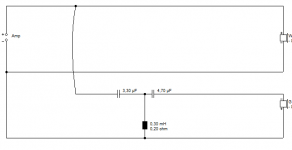
If you've got 4.7uF series, coil parallel, then 3.3uF series, chances are that crossover point is high enough that you could safely try almost any tweeter, just have a few series resistors you can swap around so you can try to level match a new tweeter.
From the looks of that crossover, I'm going to go out on a limb and say it, but there's probably not an awful lot of engineering that went into it, so I'd guess some experimentation probably won't yield any results much worse than the original.
I think you've got that right, DrDyna and Richidoo. And it shouldn't be too hard to bodge new tweeters onto that horn. You'd need to know the dome diameter for a start. Say 19mm or 27mm. Then add an attenuator if required. 
Looks like 3.3uF/0.3mH/4.7uF third order butterworth tweeter filter or thereabouts to me. Not unknown to wire that in parallel with a free running woofer: H1411-08 A26RE4
Always a bit hard to guess the polarity on acoustic BW3, either can work. So stick to the original. Or choose what sounds nicest, but my money is on negative polarity here.
Attachments
Last edited:
The tweeters are yellow and blue. The woofer is red and black.Is the woofer lead the yellow and black? It looks as though the woofer is connected directly to the terminals, both caps and coil are for the tweeter.
If you've got 4.7uF series, coil parallel, then 3.3uF series, chances are that crossover point is high enough that you could safely try almost any tweeter, just have a few series resistors you can swap around so you can try to level match a new tweeter.
From the looks of that crossover, I'm going to go out on a limb and say it, but there's probably not an awful lot of engineering that went into it, so I'd guess some experimentation probably won't yield any results much worse than the original.
- Status
- This old topic is closed. If you want to reopen this topic, contact a moderator using the "Report Post" button.
- Home
- Loudspeakers
- Multi-Way
- Crossover without documentation