As owner of Acoustic Elegance I get to see lots of incredible systems on a daily basis. Some commercial systems using our woofers have reached the $600,000 price point. Other DIY systems can rival many of those as well. As much as I enjoy helping others make successful speakers, it is a rare occasion that I get to have fun and build something for myself. The last pair of speakers I actually built for myself were started back in 1998. That was before Stryke or AE existed and Lambda Acoustics had just started. Those speakers used a pair of Vifa P17SJ in MTM alignment. I brought them to a get together at Tom Danley's house and some of the contacts I met there were what got me into where I am today.
For years now people have been buying the Dipole woofers for open baffle. From 2005-2012 I sold maybe 40 of the Dipole series woofers. They were always an offering but nobody used them much. Most people didn't know what to do with open baffle designs. Then one day we got contacted by someone who wanted to use them in a commercial system. They became the bottom end to the Lotus Group Granada along with the ultra expensive $30,000 Feastrex Field coil drivers. After their great review with many best in show nods at CES I sold as many Dipole12's the next month as I had in the past 7 years. Apparently providing the low end in a $150,000 pair of speakers doesn't hurt their apparent value. Shortly after that, SoulSonic Speakers put them in their Impact and Impulse models that got similar reviews and high price tags. Kyron Audio featured them in their Gaia and then later the Kronos models. More recently Martin King built his Project 10 using the Dipole15's for the low end along with a Lowther and made the statement "For this new system I decided to step up to probably the best dipole woofer money can buy, the Acoustic Elegance Dipole 15." It seems the reputation of the Dipole woofers is firmly established.
Over the past few years I have assisted many DIY users to build their own successful open baffle speakers. Single driver open baffles assisted by a subwoofer and multi driver arrays that can reach to low frequencies with ease are frequent requests. Many others wish they could try an open baffle but are intimidated by the unknown. I get the same questions about baffle rolloff, baffle size, baffle types such as U frame, H frame, Ripole, or flat open baffles. What it really comes down to is that people want something they can build that is a proven design that works. For the most part they don't care how that happens. I wanted to make something they could follow as a DIYer that gives them the confidence to build it because of known results.
In reality, I also want to build something for myself. I have a pair of Seas Loki kits with premade cabinets from Madisound in my living room. While they are good, I want something a little more exciting. I figured this was the perfect opportunity to build something for myself, and something that others could benefit from.
Goals:
Flexibility
For this system, I wanted something that is flexible. Right now I live in an apartment. I can't have an overly high amount of output at this time so a single woofer will probably be just fine. I don't want to limit to always having one woofer though. I hope someday soon to get married, buy a house, and have something as large as Jessica will allow me to have in the house. That means I want something that can be expandable or modular. Others have the same desires and often same questions. "what if one woofer per side isn't enough?" This design allows me to stack multiple modules together. A single woofer can be placed on the floor. A second mid/high module can be stacked right on top of it to form a complete speaker. If desired, 2 modules can be stacked underneath the mid/high module. If that isn't enough I can add 2 more modules on top of the mid/high module to make a massive tower.
Also with this modular flexibility is the ability to use whatever I want for the mid/high section. The current plan is for the Dipole6 along with a Mundorf AMT for a full open baffle system. I would love to play with some of the others that people are using though too like the Lowther or other fullrange. I don't have to make a completely new cabinet to do that, only a new module.
Design:
There are many theories on how the best open baffle should be done. Some want minimal or "naked" baffles. Some go as large as possible to get the most low end possible. For the most part I lean more towards the second opinion. The biggest issue I see is the extreme excursion need to overcome the rolloff of the baffle. The smaller the baffle the more issue you run into with distortion at high excursions and limited headroom. I don't want the baffle to take up the entire room though either. I settled on a U shaped baffle to keep the width down but to increase the distance between the front and rear wave. It also allows me to come up with a nice look.
I needed something appealing visually. I recently did a couple piano black P1512 cabinets that turned out quite nice. I really like the appearance of the large 3" radius corners. I can add 2 more corners in back and terminate it nicely so a grill can cover the back opening.
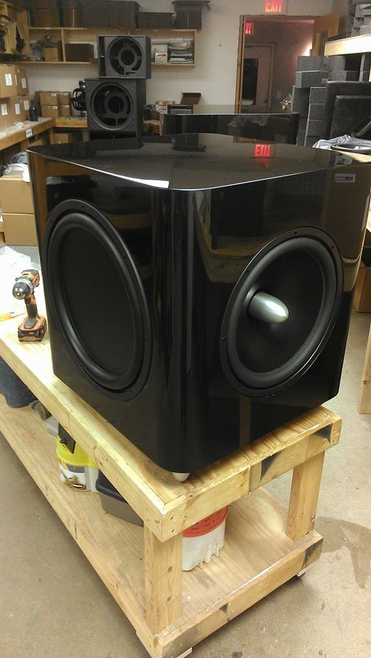
I also wanted to flare into the woofer and rear mount it. The large radius with the additional flare in to the woofer should look great when painted and buffed out.
Finish:
I love the gloss black look but wanted something a little more unique. It turns out we are about to paint Jessica's Jeep Cherokee. We ended up picking out the Porsche Meteor Grey Metallic. Basically a gunmetal grey. We will have some left over and I think that will make a nice contrast to the woofers.

One of the other things that always bothers me is MDF seams coming back. It takes so long to prepare the surface and over time the seams may reappear with temperature and moisture changes. To eliminate that and give a nice look I decided to hide all seams by having a solid wood top and bottom plate. The other nice thing is that I can then always unbolt the wood pieces if I need different ones. I haven't decided yet whether I want to stack the modules with wood panels between them or just bolt them together and have one wood cap at top and bottom. I will see that as I get a little further in on the project.
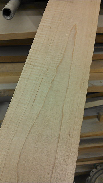
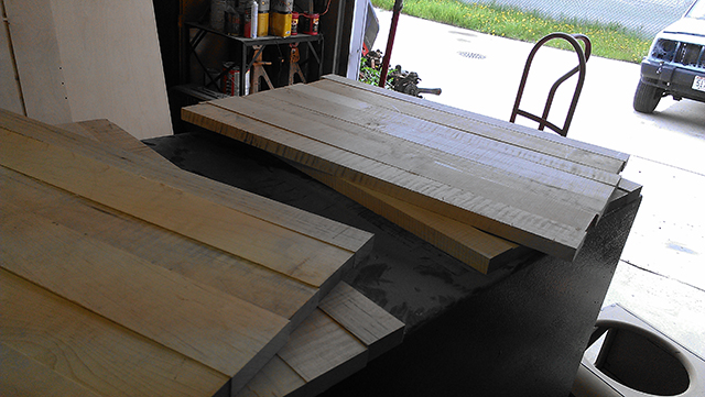
For now, I have some heavily curly maple that has been sitting for some time. I have always liked the look of grey/gunmetal along with maple. I figure this is a good project to use up the maple on. The top/bottom plates will be made out of this:
Lets Get Started!
So with all of that done, I came up with a reasonable sized baffle. While I did a few rough models with The Edge by Tolvan, I wasn't that concerned with the models. This will be a DSP based system to compensate for the baffle rolloff. I would rather rely on real measurements than the theory for this. I wanted to know approximately where I was at though. The overall dimensions are 23" wide, 16" deep and 18" tall per each module without the top/bottom wood caps. That puts the mid/high module at a pretty good height if set on top of 2 of them. With a single woofer module I can put some feet under it or have some blank space on the mid/high module for now. The large 3" radius corners really make it look smaller than if it was a rectangular shaped cabinet.
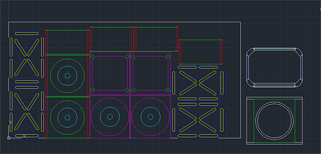
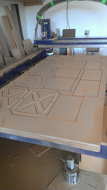
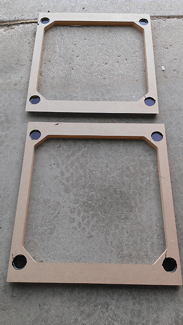
So, I drew it all out in autocad and laid out the parts for on the CNC. Then I spent a week diagnosing issues with the ShopBot, but that is another story. I can get a pair of modules out of a single 4x8 sheet of MDF. I did want to make sure that these top/bottom pieces and the modules don't rattle. I ordered some 1" wide x 1/2" thick foam tape that could keep them from rattling while still allowing them to be taken apart at any time. I then recessed an area 1/8" into the top/bottom for it to sit evenly in. A lot of the other area was removed to make sure it couldn't make contact and rattle. The holes in the top/bottom also allow wire to get run between drivers more easily. Here is the layout:
I got started and cut the first sheet that has all pieces for 2 modules.
I cleaned up the pieces and got them all ready for assembly. The first step was putting in magnets for a grill in back. I have been using a bunch of 1"x5/8" neo magnets for awhile for holding grills. Magnets can go on one side and a steel blank on the other, or magnets on both sides for extra holding power. I buried the magnets in the back panel of the baffle and filled with epoxy around them.
Once that dried it was time to put the box together. It was assembled with a black epoxy we use for many things. It holds well, is very thick so it stays in cracks, but takes awhile to dry. I still find it is the best adhesive we have used for cabinets in all the years I have been building. I have determined I am going to build a couple jigs before I assemble more modules but the first one went together quite well.
That is where my progress sits for now. I will get a few jigs together and build the second module once time permits. First though I will sand this one up so it is ready and I can put a driver in to begin testing. I will probably make a blank MDF top/bottom quickly for testing purposes but I plan to start work on the curly maple top/bottom soon as well.
I am not sure how long it will take to get this project completed but it is a priority of mine. I am hoping I can begin the measurements of this module this week. My initial goal is to hook one per channel up and use them along with the Seas coax drivers from the Loki kits. I will probably make an open baffle module for those as well but for initial testing purposes will just set the Loki on top.
I am sure people will ask, yes this will be something with plans that you can make also. I probably won't suggest the 3" radius corners for a DIY builder because it does get more difficult than with butt or dado joints. Once I get my own version done here with all the fancy bells and whistles I will get a much more simple DIY plan together that anyone could do with a circular saw and router with circle jig. For now I am just wanting to share the project of the first system I have built for myself in well over a decade.
I will update as soon as I have some more progress. That could be tomorrow unless I decide to go fishing. Happy Memorial Day to everyone!
For years now people have been buying the Dipole woofers for open baffle. From 2005-2012 I sold maybe 40 of the Dipole series woofers. They were always an offering but nobody used them much. Most people didn't know what to do with open baffle designs. Then one day we got contacted by someone who wanted to use them in a commercial system. They became the bottom end to the Lotus Group Granada along with the ultra expensive $30,000 Feastrex Field coil drivers. After their great review with many best in show nods at CES I sold as many Dipole12's the next month as I had in the past 7 years. Apparently providing the low end in a $150,000 pair of speakers doesn't hurt their apparent value. Shortly after that, SoulSonic Speakers put them in their Impact and Impulse models that got similar reviews and high price tags. Kyron Audio featured them in their Gaia and then later the Kronos models. More recently Martin King built his Project 10 using the Dipole15's for the low end along with a Lowther and made the statement "For this new system I decided to step up to probably the best dipole woofer money can buy, the Acoustic Elegance Dipole 15." It seems the reputation of the Dipole woofers is firmly established.
Over the past few years I have assisted many DIY users to build their own successful open baffle speakers. Single driver open baffles assisted by a subwoofer and multi driver arrays that can reach to low frequencies with ease are frequent requests. Many others wish they could try an open baffle but are intimidated by the unknown. I get the same questions about baffle rolloff, baffle size, baffle types such as U frame, H frame, Ripole, or flat open baffles. What it really comes down to is that people want something they can build that is a proven design that works. For the most part they don't care how that happens. I wanted to make something they could follow as a DIYer that gives them the confidence to build it because of known results.
In reality, I also want to build something for myself. I have a pair of Seas Loki kits with premade cabinets from Madisound in my living room. While they are good, I want something a little more exciting. I figured this was the perfect opportunity to build something for myself, and something that others could benefit from.
Goals:
Flexibility
For this system, I wanted something that is flexible. Right now I live in an apartment. I can't have an overly high amount of output at this time so a single woofer will probably be just fine. I don't want to limit to always having one woofer though. I hope someday soon to get married, buy a house, and have something as large as Jessica will allow me to have in the house. That means I want something that can be expandable or modular. Others have the same desires and often same questions. "what if one woofer per side isn't enough?" This design allows me to stack multiple modules together. A single woofer can be placed on the floor. A second mid/high module can be stacked right on top of it to form a complete speaker. If desired, 2 modules can be stacked underneath the mid/high module. If that isn't enough I can add 2 more modules on top of the mid/high module to make a massive tower.
Also with this modular flexibility is the ability to use whatever I want for the mid/high section. The current plan is for the Dipole6 along with a Mundorf AMT for a full open baffle system. I would love to play with some of the others that people are using though too like the Lowther or other fullrange. I don't have to make a completely new cabinet to do that, only a new module.
Design:
There are many theories on how the best open baffle should be done. Some want minimal or "naked" baffles. Some go as large as possible to get the most low end possible. For the most part I lean more towards the second opinion. The biggest issue I see is the extreme excursion need to overcome the rolloff of the baffle. The smaller the baffle the more issue you run into with distortion at high excursions and limited headroom. I don't want the baffle to take up the entire room though either. I settled on a U shaped baffle to keep the width down but to increase the distance between the front and rear wave. It also allows me to come up with a nice look.
I needed something appealing visually. I recently did a couple piano black P1512 cabinets that turned out quite nice. I really like the appearance of the large 3" radius corners. I can add 2 more corners in back and terminate it nicely so a grill can cover the back opening.
I also wanted to flare into the woofer and rear mount it. The large radius with the additional flare in to the woofer should look great when painted and buffed out.
Finish:
I love the gloss black look but wanted something a little more unique. It turns out we are about to paint Jessica's Jeep Cherokee. We ended up picking out the Porsche Meteor Grey Metallic. Basically a gunmetal grey. We will have some left over and I think that will make a nice contrast to the woofers.
One of the other things that always bothers me is MDF seams coming back. It takes so long to prepare the surface and over time the seams may reappear with temperature and moisture changes. To eliminate that and give a nice look I decided to hide all seams by having a solid wood top and bottom plate. The other nice thing is that I can then always unbolt the wood pieces if I need different ones. I haven't decided yet whether I want to stack the modules with wood panels between them or just bolt them together and have one wood cap at top and bottom. I will see that as I get a little further in on the project.
For now, I have some heavily curly maple that has been sitting for some time. I have always liked the look of grey/gunmetal along with maple. I figure this is a good project to use up the maple on. The top/bottom plates will be made out of this:
Lets Get Started!
So with all of that done, I came up with a reasonable sized baffle. While I did a few rough models with The Edge by Tolvan, I wasn't that concerned with the models. This will be a DSP based system to compensate for the baffle rolloff. I would rather rely on real measurements than the theory for this. I wanted to know approximately where I was at though. The overall dimensions are 23" wide, 16" deep and 18" tall per each module without the top/bottom wood caps. That puts the mid/high module at a pretty good height if set on top of 2 of them. With a single woofer module I can put some feet under it or have some blank space on the mid/high module for now. The large 3" radius corners really make it look smaller than if it was a rectangular shaped cabinet.
So, I drew it all out in autocad and laid out the parts for on the CNC. Then I spent a week diagnosing issues with the ShopBot, but that is another story. I can get a pair of modules out of a single 4x8 sheet of MDF. I did want to make sure that these top/bottom pieces and the modules don't rattle. I ordered some 1" wide x 1/2" thick foam tape that could keep them from rattling while still allowing them to be taken apart at any time. I then recessed an area 1/8" into the top/bottom for it to sit evenly in. A lot of the other area was removed to make sure it couldn't make contact and rattle. The holes in the top/bottom also allow wire to get run between drivers more easily. Here is the layout:
I got started and cut the first sheet that has all pieces for 2 modules.
I cleaned up the pieces and got them all ready for assembly. The first step was putting in magnets for a grill in back. I have been using a bunch of 1"x5/8" neo magnets for awhile for holding grills. Magnets can go on one side and a steel blank on the other, or magnets on both sides for extra holding power. I buried the magnets in the back panel of the baffle and filled with epoxy around them.
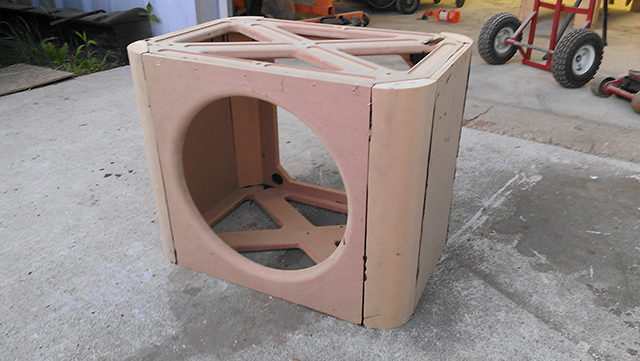
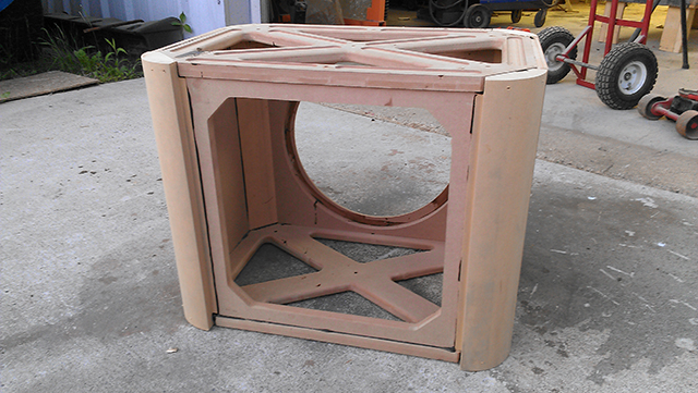
Once that dried it was time to put the box together. It was assembled with a black epoxy we use for many things. It holds well, is very thick so it stays in cracks, but takes awhile to dry. I still find it is the best adhesive we have used for cabinets in all the years I have been building. I have determined I am going to build a couple jigs before I assemble more modules but the first one went together quite well.
That is where my progress sits for now. I will get a few jigs together and build the second module once time permits. First though I will sand this one up so it is ready and I can put a driver in to begin testing. I will probably make a blank MDF top/bottom quickly for testing purposes but I plan to start work on the curly maple top/bottom soon as well.
I am not sure how long it will take to get this project completed but it is a priority of mine. I am hoping I can begin the measurements of this module this week. My initial goal is to hook one per channel up and use them along with the Seas coax drivers from the Loki kits. I will probably make an open baffle module for those as well but for initial testing purposes will just set the Loki on top.
I am sure people will ask, yes this will be something with plans that you can make also. I probably won't suggest the 3" radius corners for a DIY builder because it does get more difficult than with butt or dado joints. Once I get my own version done here with all the fancy bells and whistles I will get a much more simple DIY plan together that anyone could do with a circular saw and router with circle jig. For now I am just wanting to share the project of the first system I have built for myself in well over a decade.
I will update as soon as I have some more progress. That could be tomorrow unless I decide to go fishing. Happy Memorial Day to everyone!
Can't wait to see the final results! Our 2002 Grand Cherokee Overland is a similar Graphite Metallic and quite handsome so I am looking forward to seeing how this turns out. So a 12" version of this kit will be available?
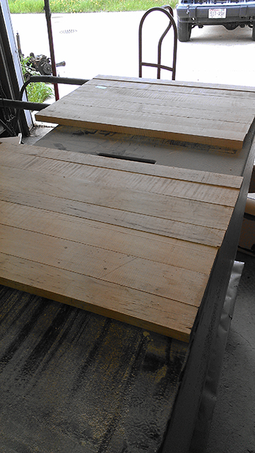
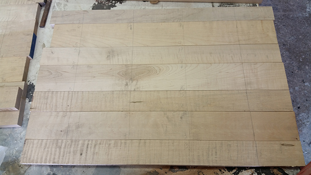
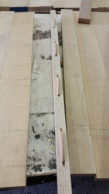
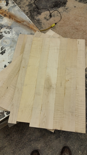
I got a little time in today, but not much. Just enough to dig out the rest of the curly maple off of the wood rack. I then cut the pieces to 25" long. The top will be 23" finished width so I needed a little more length to screw down to the CNC table when cutting the shape out. I ripped them down to somewhat random widths. I did make the pieces symmetrical but this was more about not wasting too much material than it was about having perfect symmetry to the pieces. They range in width from about 2.25" to 3.5". I laid them out for 4 total pieces, two tops and two bottoms. The curly maple really is quite nice looking. The nice thing is with the modular design I can easily end up with 4 tops instead of using these as 2 bottoms. Later on I will probably do that and make the bottom plates out of plain maple when I get more in.
That's all the progress for today. Time to get outside in the nice weather. Tomorrow I plan to run everything through the jointer so they are ready to glue up. I plan to use biscuits when gluing the pieces all together. I will then take them and have them sanded to thickness by a local shop with a large sander. I don't want to attempt to plane something like this. With all the curls in the wood that never turns out very good. I definitely don't want big chips out of the surface.
That's all the progress for today. Time to get outside in the nice weather. Tomorrow I plan to run everything through the jointer so they are ready to glue up. I plan to use biscuits when gluing the pieces all together. I will then take them and have them sanded to thickness by a local shop with a large sander. I don't want to attempt to plane something like this. With all the curls in the wood that never turns out very good. I definitely don't want big chips out of the surface.
It's a bit of a stretch to imagine that a woofer manufacturer is worried about excursion requirements. 🙂 There's a reason why minimal baffles have such a large following.
I'd wager John has pretty much heard them all.There's a reason why minimal baffles have such a large following.
John, what are your intended xo points?
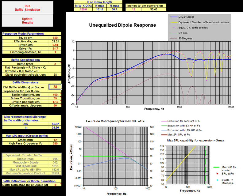
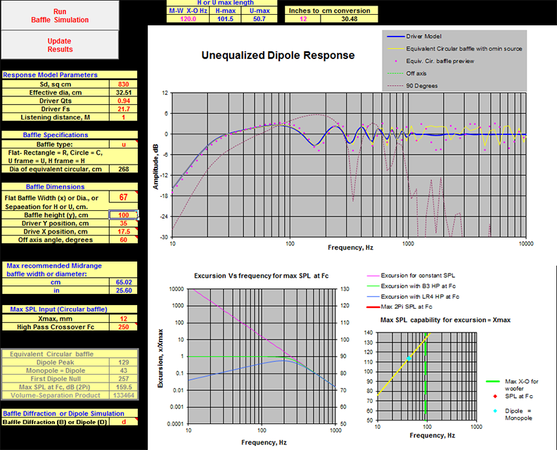
As mentioned, there are benefits to the minimal or naked baffle mostly in the dipole radiation pattern. The problem is that you simply cannot get enough output from it. While I do want to verify with actual measurements, the models show a huge difference in output between the U baffle and naked circular baffle. This should be the case due to the large separation difference between them. If I was to take a 15" woofer on a tiny baffle vs the U frame that is being made, there is an 18dB difference in modeled maximum output at 20hz. A single Dipole15 with the naked baffle can only achieve about 75dB at 20hz. This just isn't very useful.
The U baffle on the other hand shows I can achieve about 95dB at 20hz with this design. Again, this needs to be verified as these estimates seem extremely generous. If 95dB can be achieved from one woofer, this may be enough for many people. Again this is where the modular design comes in and multiples can be stacked based on the needs. To get the same output with naked baffles would take 6x as many drivers. Again that isn't very practical.
Having the most ideal dipole radiation pattern but not being able to achieve required output levels really doesn't mean much. Reflections in the room really mess up this radiation pattern as well. If you are going to those efforts realize that there are many other factors beside just the baffle. Another of the large benefits is simply eliminating resonances and reflections in the enclosure coming back through the cone at a delay. Eliminating this is still a huge benefit. That is what most are achieving in their designs.
![Impulse%20white%20MB%20(1)%20[1024x768].jpg](/community/proxy.php?image=http%3A%2F%2Fwww.soulsonicspeakers.com%2Fimages%2FImpulse%2520white%2520MB%2520%281%29%2520%5B1024x768%5D.jpg&hash=81683c23a532088e8b332c24ea221f15)
It is all about compromises.
The U baffle on the other hand shows I can achieve about 95dB at 20hz with this design. Again, this needs to be verified as these estimates seem extremely generous. If 95dB can be achieved from one woofer, this may be enough for many people. Again this is where the modular design comes in and multiples can be stacked based on the needs. To get the same output with naked baffles would take 6x as many drivers. Again that isn't very practical.
Having the most ideal dipole radiation pattern but not being able to achieve required output levels really doesn't mean much. Reflections in the room really mess up this radiation pattern as well. If you are going to those efforts realize that there are many other factors beside just the baffle. Another of the large benefits is simply eliminating resonances and reflections in the enclosure coming back through the cone at a delay. Eliminating this is still a huge benefit. That is what most are achieving in their designs.
An externally hosted image should be here but it was not working when we last tested it.
It is all about compromises.
Baffle-less designs are for those wanting to take it to the extreme (i.e. dipole purists). Of course you would want as much baffle as possible, until the dipole peak drops low enough to get into your passband.
I haven't been able to get much done on this but finally got some time yesterday to do a little. The next step was to actually glue up the curly maple top and bottom caps. I took all the boards and laid them out with end grain properly altered. I then drew lines to use as guides for the #20 biscuits used to help align them. I ran each board through the jointer taking off the smallest amount possible to remove any saw cuts assuring a proper seam when glued.
Then I took out the porter cable biscuit jointer and made all the slots for the biscuits.
Then using some Titebond III I glued them all up. Boards were clamped top and bottom to keep the assembled panel from bowing with pressure from the clamps.
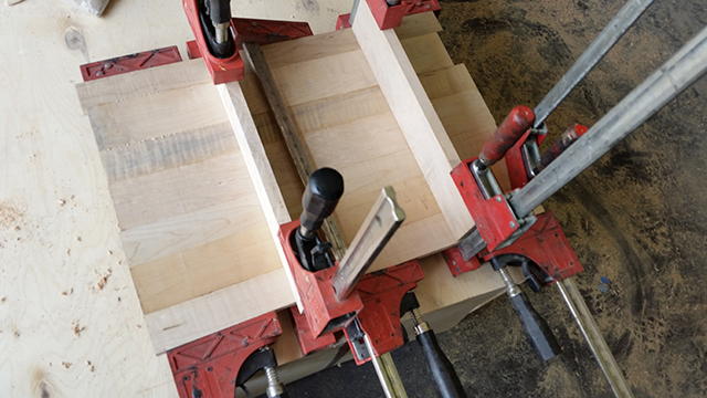
The end result was 4 nicely glued panels.
Because these are curly maple I can't really plane to thickness. Luckily, there is a local shop that has a very nice 50" wide triple belt sander and a 50" wide rotary sander as well. For about $20 they will send the panels through the belt sander multiple passes until they are smooth, then send through the rotary sander to remove the sanding lines. Then it is back to the shop for these panels to go on the CNC router where they will be taken down to the final shape to match the curves of the enclosure.
Then I took out the porter cable biscuit jointer and made all the slots for the biscuits.
Then using some Titebond III I glued them all up. Boards were clamped top and bottom to keep the assembled panel from bowing with pressure from the clamps.
The end result was 4 nicely glued panels.
Because these are curly maple I can't really plane to thickness. Luckily, there is a local shop that has a very nice 50" wide triple belt sander and a 50" wide rotary sander as well. For about $20 they will send the panels through the belt sander multiple passes until they are smooth, then send through the rotary sander to remove the sanding lines. Then it is back to the shop for these panels to go on the CNC router where they will be taken down to the final shape to match the curves of the enclosure.
Thanks for the link to this thread John. I think the U baffles will work great with my horns. Look forward to seeing the final results.
Hey John did you ever get these built? Seem's the thread died last year while some of us lurkers have waited to see and hear about your final results. How about an update 🙂
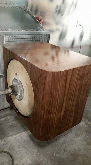
After a long delay, I finally had a chance to do some work on a new set of UB151 that were veneered in a black walnut. The design is very similar without the removable top/bottom. For all practical purposes, the performance is identical between the two versions. They are just cosmetically different options. Here is the build process that I went through on this set.
After assembling the cabinets, the first thing done was to prep them for veneer. While the veneer will cover very tiny flaws, a great amount of care needs to be done in prepping the MDF. Seams tend to telegraph through if the cabinet is not sealed properly. I ended up spraying them with a catalyzed polyurethane sanding sealer that was diluted with MEK. This allows the sanding sealer to penetrate into the MDF much further, rather than sitting on the surface. It is sprayed on heavily with the intent of soaking the MDF. As a result, it will run. This is not a problem as the sanding sealer sands very easily and final body work is done after this step anyway.
While these are fully curing, the veneer is cut to size to perform the wrap of the cabinets. It is laid out upside down to help flatten prior to applying it to the cabinets.
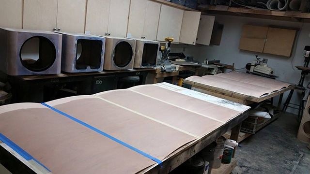
Next, the final body work is done over the top of the sealer and the whole cabinet is blocked out by hand. We use Rage Gold body filler and Icing finishing filler. They are more expensive than some other fillers but they lay down smoothly and sand very easily. Here the cabinets are all sanded, filled, and ready for adhesive.
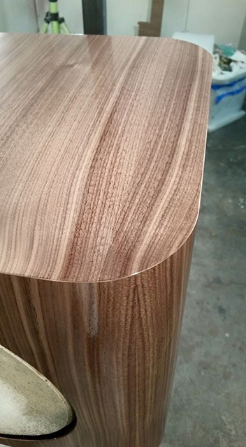
I then did a wrap with the NBL backed walnut veneer. As these cabinets will be stacked, I sequenced the veneer to give a continual grain over the front of the cabinets. You can see the grain pattern more continually before the cutouts were made.
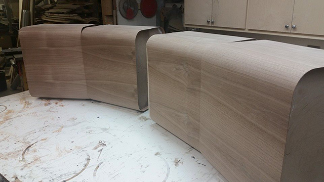
From there, the veneer was trimmed for the driver holes and the open back of each cabinet. Magnetic grills will cover the openings in back to give them a finished look.

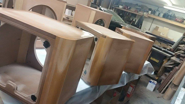
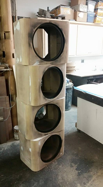
The cabinets where then taken to the spray area and hung on the rack. This allows for all sides of the cabinet to be sprayed simply by rolling the cabinet on the bearings. Two coats of sanding sealer were applied. The cabinets were again blocked out by hand. Two final coats of a 45 degree sheen top coat were then applied to finish the cabinets. The result is a finish between satin and semi gloss with very deep grain.
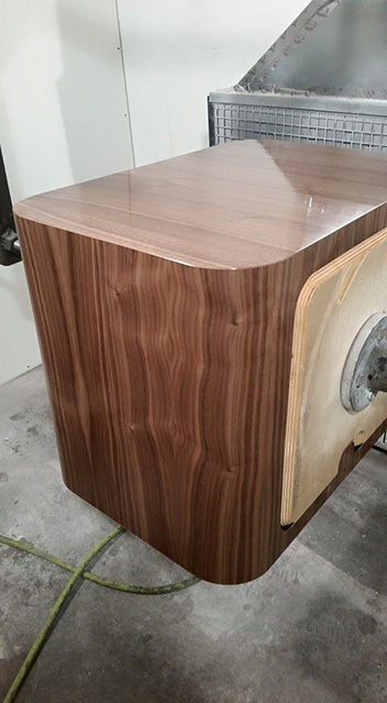
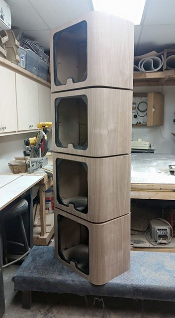
I had a little time so I was able to stack the baffles showing the possibility for 4x UB151 to be done in a single stack with sequenced veneer. The design and large radius corners ended up looking very nice.
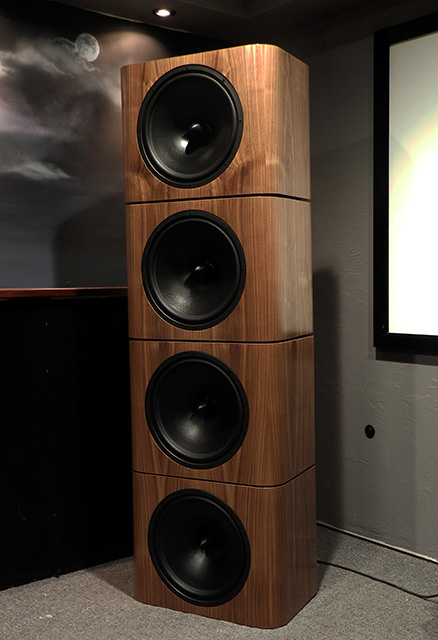
To get somewhat of an idea of their performance as the bottom end with a horn based system I took the cabinets and stacked 2 per side under the Radian 745BePB on the SEOS24 waveguides. Unfortunately I did not get to spend significant time optimizing this system, but the initial results were very promising.
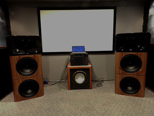
I will be getting some good measurments of the UB151 soon in a very large room, or outdoors. While they produced tremendous bass in the small demo room, it as not at all ideal for taking these measurements.
After assembling the cabinets, the first thing done was to prep them for veneer. While the veneer will cover very tiny flaws, a great amount of care needs to be done in prepping the MDF. Seams tend to telegraph through if the cabinet is not sealed properly. I ended up spraying them with a catalyzed polyurethane sanding sealer that was diluted with MEK. This allows the sanding sealer to penetrate into the MDF much further, rather than sitting on the surface. It is sprayed on heavily with the intent of soaking the MDF. As a result, it will run. This is not a problem as the sanding sealer sands very easily and final body work is done after this step anyway.
While these are fully curing, the veneer is cut to size to perform the wrap of the cabinets. It is laid out upside down to help flatten prior to applying it to the cabinets.
Next, the final body work is done over the top of the sealer and the whole cabinet is blocked out by hand. We use Rage Gold body filler and Icing finishing filler. They are more expensive than some other fillers but they lay down smoothly and sand very easily. Here the cabinets are all sanded, filled, and ready for adhesive.
I then did a wrap with the NBL backed walnut veneer. As these cabinets will be stacked, I sequenced the veneer to give a continual grain over the front of the cabinets. You can see the grain pattern more continually before the cutouts were made.
From there, the veneer was trimmed for the driver holes and the open back of each cabinet. Magnetic grills will cover the openings in back to give them a finished look.
The cabinets where then taken to the spray area and hung on the rack. This allows for all sides of the cabinet to be sprayed simply by rolling the cabinet on the bearings. Two coats of sanding sealer were applied. The cabinets were again blocked out by hand. Two final coats of a 45 degree sheen top coat were then applied to finish the cabinets. The result is a finish between satin and semi gloss with very deep grain.
I had a little time so I was able to stack the baffles showing the possibility for 4x UB151 to be done in a single stack with sequenced veneer. The design and large radius corners ended up looking very nice.
To get somewhat of an idea of their performance as the bottom end with a horn based system I took the cabinets and stacked 2 per side under the Radian 745BePB on the SEOS24 waveguides. Unfortunately I did not get to spend significant time optimizing this system, but the initial results were very promising.
I will be getting some good measurments of the UB151 soon in a very large room, or outdoors. While they produced tremendous bass in the small demo room, it as not at all ideal for taking these measurements.
- Status
- Not open for further replies.
- Home
- Loudspeakers
- Multi-Way
- The Genesis of the UB151 Modular Open Baffle Design