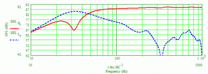
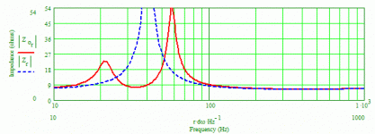
Based on my extensive modeling results, the 10-inch location is not "too much from the open end" and has shown to be essentially ideal when the line length is in the 50-60" range with the driver close to the 33% location. What I normally do is fix the driver location, whether that's at around 20% or 33%, in order to satisfy other considerations, then locate the port for the "best" response I described. A 1-inch difference in location can have a significant impact and when I'm honing in on the optimum location in the modeling, I will make incremental changes of 1/8" to 1/4" if necessary to find that optimum point.
Paul
Paul
I concur with these observations for a MLTL - the port is rarely located at the lowest point possible when looking at how clean the output is. Also, placing driver between 20% and 33% seems to work but an inch can make big difference, and the only way to tell is to simulate it. 10 inches from the bottom for port location may work, but is kind of too much from the "open" end to call it open anymore - I have gone as high as 7 or 8 inches and that is usually better than 1.5 or 2 inches.
Gee, you must be way smarter than anyone/everyone else! I guess the designs/builds I've done for personal use, the numerous designs I've done for others all around the world, and the multiple designs I've done for others to commercially produce (Salk Sound, Philharmonic Audio and Fried), almost all with the driver(s) located at 20%, that have been highly regarded, were just the result of lucky breaks or benefited from room/harmonic mode masking?  Why must a low-Q port be used, and why is a high-Q port automatically inferior? It's very, very easy to see in modeling what happens to the system performance as the port's location is varied, BTW. Why does anyone need their design criteria and actual results to be determined to be acceptable or worthy based on comparison to your criteria. I wonder, are you "villastrangiato" under another name?
Paul
Paul
If you would post up driver and enclosure info and I'll see if your design criteria match mine. I rather doubt it does, have yet to see any driver placed @20% work with a low Q port. Now if your designing a BR/TL may work (= high Q port) but even then doubt the second harmonic is nulled.
Most acoustic desings would utterly fail if RF. Only passable because of the room / harmonic node masking.
I'm willing to bet most do not understand the significance between high aspect ratio / low Q ports and low aspect ratio / high Q ports and how this affects driver placement along the line.
This time around the Peerless CX145H, with great care taken to measure the nearfield at center dome at surround level and the pipe in the geometric middle in the same plane as the exit.
As I wanted to study the harmonics, moving the driver from the start of the pipe would defeat the purpose and also complicate some of the foldings and where to place the driver.
IMF folding

The tapered line folded once

The Daline

Note the lower Q and the lower level. When I tested the two other drivers I got the impression that the output from the pipe of the DaLine was lower than from the other two that appeared to be roughly equal. I then decided to combine the 3 graphs above

The nearfield response of IMG (Blue) and DaLine (Red) and OneFold (Green) is +/- 1dB or so. The pipe output from the IMF and OneFold is simliar in level and Q at fundamental but the harmonics of the OneFold is lower. The DaLine is really different the fundamental is flatter and 5-6 dB lower than the other two as is the dip in NF, and the harmonics are strong. Any explanation for the much lower fundamental output?
As I wanted to study the harmonics, moving the driver from the start of the pipe would defeat the purpose and also complicate some of the foldings and where to place the driver.
IMF folding

The tapered line folded once

The Daline

Note the lower Q and the lower level. When I tested the two other drivers I got the impression that the output from the pipe of the DaLine was lower than from the other two that appeared to be roughly equal. I then decided to combine the 3 graphs above

The nearfield response of IMG (Blue) and DaLine (Red) and OneFold (Green) is +/- 1dB or so. The pipe output from the IMF and OneFold is simliar in level and Q at fundamental but the harmonics of the OneFold is lower. The DaLine is really different the fundamental is flatter and 5-6 dB lower than the other two as is the dip in NF, and the harmonics are strong. Any explanation for the much lower fundamental output?
Last edited:
Use Leonard Audio Transmission Line, remove .txt
Project_1: Driver @ 1/5 length, lite stuffing first third of length
Project_1a: Driver @ 1/3 length, lite stuffing first third of length
Project_1b: Driver @ 1/3 length, lite stuffing last 2/3rds of length
Project_1c: duplicate of 1b (disregard)
Project_1d: Driver @ 1/3 length, port 2" dia x 6"
Project_1e: Driver @ 1/3 length, port 2" dia x 4"
Project_1f: correctly done.
Sims done with only 3watts
Attachments
Last edited:
I thought I might do some experiments damping the first section of the pipe of the IMF fold. In the back row from left. fluffy BAF, pharmacy grade cotton and "unwashed african sheeps wool". All at 90g +/- 10g
The tree sheets at the front is top to bottom
recycled cotton fibers 100g and about 10mm thick
Accoustic grade foam 143g with paper backing the selfadhesive.
BAF sheet for bass reflex speakers 82grams about 15 mm thick and denser and coarser than the BAF roll at the back. Not Scotchbrite but with a shape that keeps.
The aim would be to get the harmonics down as much as possible with minimal damage to the fundamental.
I was surprised that "lite stuffing last 2/3rds of length" did so little influence of the fundamental, how much is lite stuffing?

Not exactly sure myself.  Setting "custom" to 0.2 is close to the "lite" setting. Increasing it to 1 appears to be "medium" and 2 is close to "heavy" stuffing. Perhaps this density is the equivalent of 0.2lbs/ft³, 1.0lbs/ft³ and 2.0lbs/ft³.
http://www.diyaudio.com/forums/software-tools/220421-transmission-line-modelling-software.html
 Setting "custom" to 0.2 is close to the "lite" setting. Increasing it to 1 appears to be "medium" and 2 is close to "heavy" stuffing. Perhaps this density is the equivalent of 0.2lbs/ft³, 1.0lbs/ft³ and 2.0lbs/ft³.
http://www.diyaudio.com/forums/software-tools/220421-transmission-line-modelling-software.html
OK, I have to mull over those numbers to get them to metric.
Now for a very overloaded graph. Pipe output is measured with the damping material placed according to individual descriptions along the first pipe section "wools" and for the whole 59 cm internal back plane of the box for the "Sheet" materials.
Starting from the top and working my way down
Black= empty pipe
Gray= recyled felt covering the back and the side of the pipe section as well as back and about 10 cm up on sides of the back of the chamber=> does not do much does it, major dissapointment!
Blue= The BAF sheet 40x60cm covering the back and the side of the pipe section as well as back and about 10 cm up on sides of the back of the chamber =>Not bad lowers the fundamental 2 dB and 2 Hz and knocks away 8 dB of the harmonics.
Green= The Foam sheet 40x60cm covering the back and the side of the pipe section as well as back and about 10 cm up on sides of the back of the chamber =>Not bad lowers the fundamental 2 dB and 2 Hz and knocks away 8 dB of the harmonics.
Yellow=lumps of sheep wool with small twigs in it! spread along the pipe=>Good , for 1 dB lost at fundamental 4 dB more is knocked off the harmonics. Tricky to work with but now I understand why it is recomended.
Red= A sheet of cotton along the back plane=> Also good stuff!
Brown= The volume and "springyness" makes the BAF to fill up the whole volume to the pipe=> It really takes away to much, perhaps less would work better.
To do a more detailed experiment I would need to have a detachable side panel to access all parts of the chamber and pipe.
But it appears lining the chamber and first third of the pipe is a good start.

For xrk971 and Greebster
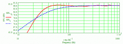
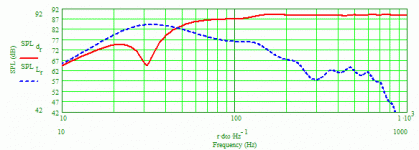
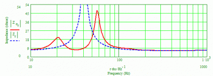
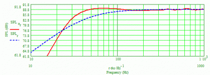
FWIW, I did some example ML-TL modeling for both of you to comment on. For xrk971 I did two sets, one with the driver located at 20% from the closed end of the line with the port near the other end, and another set with the driver located 33% from the closed end with the port 10" from the other end. The driver I modeled for is the SB Acoustics SB17 and I used Zaph Audio's (John Krutke) T/S measurements (Zaph|Audio). I modeled with 0.5 ohms added in series with the driver to simulate resistance from series crossover inductor(s) and a bit of cabling. I used Martin King's ML-TQWT modeling worksheets.
Here are the commonalities:
Line length is 55" and the line's cross-sectional area is 7"W x 5.5"D. The first half of the lines are stuffed at a density 0.75 lb/ft3 with polyester fiber. The port is 2"D x 3.75"L. The system tuning frequency is ~32 Hz. Graphs shown are for a 2.83v/1m.
There are 3 modeling graphs in each set with the first 3 graphs for the 20% driver location, and the other 3 graphs for the 33% driver location. The red line in the first graph in each set is the system bass response. In the second graph in each set, the red line is the driver's response and the dashed blue line is the port's response. The red line in the third graph is the resulting impedance. Looking at the first graph in each set it's clear the system bass responses are very similar, if not almost identical, having an F3 of ~34 Hz and pretty smooth responses (the small ripples in these curves are ~+/- 0.5 dB in magnitude).
Greebster, I don't know if these graphs and information will be enough for you to illustrate how and why your process gives better results. I can say that this modeling is pretty typical for my designs. When coupled with a moderate amount of BSC (3-3.5 dB), the resulting bass is very articulate and satisfying, never boomy or lean, no matter if the cabinets are inches or a couple feet away from the wall behind. The bass sounds virtually the same in my living room as at various DIY venues, without being bothered by room effects suffered by other designs (I'm not just tooting my own horn here as others who've heard my designs will tell you the same).
Paul
Edit: Hmm, the graphs didn't get organized as I thought they would. So, the first set of graphs are the first 3 in the top row, and the second set of graphs start with the last graph in the top row, followed by the two graphs located vertically below the very first graph in the top left corner. Also, I forgot to state that for the driver located at 20% (11" from the beginning of the line), the port's center is located 3.5" from the other end of the line. For the driver located at 33% (18.33" from the line's beginning), the port's center is 10" from the other end of the line.
Attachments
Last edited:
Thx Paul, Will look into it ASAP. Have to deal with an ~500meg update on my Android Tablet that just came through. Don't ya just love them, NOT 
***
Oh really NOT!!!, has bloody display timeout of 5 seconds, while digging through all the changes done trying to find WTHeck they put whatever at, cripes! Perhaps they shouldn't be playing with themselves when beta testing this garbage Samsung shoves out the door
***
And an Excel 2010 issue, perhaps I should do an update on it that I've been putting off for a few weeks now... another 240meg
Microsoft is just as bad. Don't install until SP1 is out
May just install Office '97, have my old CD's around here somewhere.
***
Oh really NOT!!!, has bloody display timeout of 5 seconds, while digging through all the changes done trying to find WTHeck they put whatever at, cripes! Perhaps they shouldn't be playing with themselves when beta testing this garbage Samsung shoves out the door
***
And an Excel 2010 issue, perhaps I should do an update on it that I've been putting off for a few weeks now... another 240meg
Microsoft is just as bad. Don't install until SP1 is out
May just install Office '97, have my old CD's around here somewhere.
Time for measurement of the Once Folded TLS
This time with the separate graph of the sheet material and then the whole thing.
Starting from the top and working my way down
Black= empty pipe
Gray= recyled felt covering the back and the side of the pipe => Does not harm the fundamental and cuts 3-4 dB of the harmonics, decent
Blue= The BAF sheet 40x60cm covering the back and the side of the pipe => Takes 5 dB from the 5th harmonics no effect on fundamenal and 3rd, quite bad this time
Green= The Foam sheet 40x60cm covering the back and the side of the pipe section =>Same as the BAF sheet not that good this time

Yellow=lumps of sheep wool with small twigs in it! spread along the pipe=>As bad as the foam sheet.
Red= A sheet of cotton along the back plane=> As bad as the foam sheet more or less
Brown= With the whole volume behind the driver to start as there is no chamber lefte empty here this time I could shape a narrow open channel in the middle of the pipe=> For a 2 dB loss at the fundamental I get 3rd -6dB 5th -12dB 7th -6dB

Quite interesting/disturbing that the outcome for the different materials vary so much for the two TLS that really are quite similar. I asume that TLS programs the pipe cross section as uniform that is the sound pressure and wave propagation is the same across the section. We know that around bends the wave does not follow the geometrical midline but short cuts the curve. FEM models anyone?
This time with the separate graph of the sheet material and then the whole thing.
Starting from the top and working my way down
Black= empty pipe
Gray= recyled felt covering the back and the side of the pipe => Does not harm the fundamental and cuts 3-4 dB of the harmonics, decent
Blue= The BAF sheet 40x60cm covering the back and the side of the pipe => Takes 5 dB from the 5th harmonics no effect on fundamenal and 3rd, quite bad this time
Green= The Foam sheet 40x60cm covering the back and the side of the pipe section =>Same as the BAF sheet not that good this time

Yellow=lumps of sheep wool with small twigs in it! spread along the pipe=>As bad as the foam sheet.
Red= A sheet of cotton along the back plane=> As bad as the foam sheet more or less
Brown= With the whole volume behind the driver to start as there is no chamber lefte empty here this time I could shape a narrow open channel in the middle of the pipe=> For a 2 dB loss at the fundamental I get 3rd -6dB 5th -12dB 7th -6dB

Quite interesting/disturbing that the outcome for the different materials vary so much for the two TLS that really are quite similar. I asume that TLS programs the pipe cross section as uniform that is the sound pressure and wave propagation is the same across the section. We know that around bends the wave does not follow the geometrical midline but short cuts the curve. FEM models anyone?
Last edited:
I realised that the back wall behind the driver is the "outer curve" of the IMF fold and the inner curve of the Onefold TLS. So in a way the damping material has been on opposite sides of the first fold for the two TLS.
The tests I did suggest that there is a slight difference for the BAF sheet and felt depending on if they are one the front or inner wall of the first section. But with the limited access throug the 120mm hole for the speaker it is really hard to get the felt applied consistently without creases and folds. So to do this properly I would need to have a removable side panel that would close consistently as I discovered with the M. J King compact BLH. But I have a hunch that how you put damping material is as important as were you put it.
I think it is time to move on and take a practical look at that Decca Corner Horn. This time thinking ahead about access to cabinet for adding damping material and other things. Perhaps removable top and bottom panels.
Last edited:
Paul, the ER18 happens to be one of my favorite drivers. Very similar specs to one I'm currently testing. Problem is looking at your sims, without seeing it all so to speak deems problematic. To tweak it out like I do requires more sim info. Can say I get quite close with a tad more length, damped differently, driver placement offset further down the line.
BTW I have no doubts as to the clean sound your sims yield in the real world.
Was expecting to cut up some test bins yesterday, when I somehow threw my back out... again, third time in the last two weeks. Around 9pm lastnight was in so much pain nothing helped, laying down, sitting or standing. Already maxed out on meds for a few more hours ended up getting out my heating pad, only to discover the significant other had killed it. Great. She wanted to run to the store by 9:30 and buy another... it's only $20 (another and another and another, cripes). Said no. So I tore that bugger apart and resoldered the crap wires to the thermal limiters. Fixed in 15min, half the time it would have taken her to buy another.
Today I'm way better, but it's one of those things that you are more afraid todo anything that may irritate it again. You know that OMG antsy feeling it may let go at any minute.
Well I'm not completely down and out. Will see what can get done. Was headed outside for some measurements earlier and the Cicada's are making a racket (too windy also). Something on the order of ~85dB when they get wound up. Today might be best suited to solving a few software issues, Office 2010, Virtual Box, etc. Rain is expected in about 3 hours anyway (same as yesterday)
BTW I have no doubts as to the clean sound your sims yield in the real world.
Was expecting to cut up some test bins yesterday, when I somehow threw my back out... again, third time in the last two weeks. Around 9pm lastnight was in so much pain nothing helped, laying down, sitting or standing. Already maxed out on meds for a few more hours ended up getting out my heating pad, only to discover the significant other had killed it. Great. She wanted to run to the store by 9:30 and buy another... it's only $20 (another and another and another, cripes). Said no. So I tore that bugger apart and resoldered the crap wires to the thermal limiters. Fixed in 15min, half the time it would have taken her to buy another.
Today I'm way better, but it's one of those things that you are more afraid todo anything that may irritate it again. You know that OMG antsy feeling it may let go at any minute.

Well I'm not completely down and out. Will see what can get done. Was headed outside for some measurements earlier and the Cicada's are making a racket (too windy also). Something on the order of ~85dB when they get wound up. Today might be best suited to solving a few software issues, Office 2010, Virtual Box, etc. Rain is expected in about 3 hours anyway (same as yesterday)
I realised that the back wall behind the driver is the "outer curve" of the IMF fold and the inner curve of the Onefold TLS. So in a way the damping material has been on opposite sides of the first fold for the two TLS.
The tests I did suggest that there is a slight difference for the BAF sheet and felt depending on if they are one the front or inner wall of the first section. But with the limited access throug the 120mm hole for the speaker it is really hard to get the felt applied consistently without creases and folds. So to do this properly I would need to have a removable side panel that would close consistently as I discovered with the M. J King compact BLH. But I have a hunch that how you put damping material is as important as were you put it.
I think it is time to move on and take a practical look at that Decca Corner Horn. This time thinking ahead about access to cabinet for adding damping material and other things. Perhaps removable top and bottom panels.
That's the tedious nature of dampening tests. Might be better to place the port on the backside and make the front baffle extra long and removable. This way you could also shift the driver position up / down and change dampening.
ER18 or SB17?
I modeled for the SB Acoustics SB17RNX--- but it appears from your statement you're thinking it was the ER18? Whatever the driver, exactly how much more and what specific info do you need? You can access the T/S values I used for the SB17 from Zaph Audio and I listed all pertinent data for the line configuration, driver and port locations, stuffing density/length and port dimensions. I'm at a loss for what else there could possibly be!
Paul
Paul, the ER18 happens to be one of my favorite drivers. Very similar specs to one I'm currently testing. Problem is looking at your sims, without seeing it all so to speak deems problematic. To tweak it out like I do requires more sim info. Can say I get quite close with a tad more length, damped differently, driver placement offset further down the line.
BTW I have no doubts as to the clean sound your sims yield in the real world.
Was expecting to cut up some test bins yesterday, when I somehow threw my back out... again, third time in the last two weeks. Around 9pm lastnight was in so much pain nothing helped, laying down, sitting or standing. Already maxed out on meds for a few more hours ended up getting out my heating pad, only to discover the significant other had killed it. Great. She wanted to run to the store by 9:30 and buy another... it's only $20 (another and another and another, cripes). Said no. So I tore that bugger apart and resoldered the crap wires to the thermal limiters. Fixed in 15min, half the time it would have taken her to buy another.
Today I'm way better, but it's one of those things that you are more afraid todo anything that may irritate it again. You know that OMG antsy feeling it may let go at any minute.
Well I'm not completely down and out. Will see what can get done. Was headed outside for some measurements earlier and the Cicada's are making a racket (too windy also). Something on the order of ~85dB when they get wound up. Today might be best suited to solving a few software issues, Office 2010, Virtual Box, etc. Rain is expected in about 3 hours anyway (same as yesterday)
- Status
- This old topic is closed. If you want to reopen this topic, contact a moderator using the "Report Post" button.
- Home
- Loudspeakers
- Multi-Way
- Pipe fold geometries and harmonic patterns
