So I'm about to put in an order with PE for the crossover components in my newly acquired Genesis Physics II's.
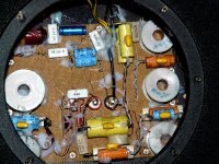
I'm glad to see that Genesis used air core inductors and I would reuse them if I could, but they are so heavily glued onto the terminal board, it's going to be impossible to get them off without breaking them. Not only that, but I would rather just keep the original terminal board and crossover intact just because.
I'm not going crazy on the caps as there's only one, a 10uF on the tweeter (the woofer runs fullrange). For the cap, I'm just going to use a single Dayton PMPC-10 10uF 1% cap.
Now for the question...
It says in the schematic that these inductors are 0.47mH and wound with 22awg wire. Would there be any harm in going with larger 15awg inductors? Since these are on the tweeters, would I benefit from moving up to the foil inductors over the standard 15awg wire inductors? They're only a few bucks more.
As a side note, I'm not going to be incorporating the attenuation switch for the tweeter. With the somewhat plush furnishings, cat tree and carpet in our apartment, the tweeters sound just fine wide open. Then again, I can't tell any difference when I flip the switch either.
One last thing, and this may come a little later down the road, but I was thinking of possibly upgrading to the new aluminum tweeter, but only if there's a real improvement over the 30 year old original phenolic tweeters. Any thoughts on this one?
Many thanks in advance!
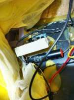
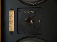
Here's an inside pic as well as a quick system pic, both taken by my iPhone and uploaded to my PC automatically via iCloud. A very awesome app I must say! Anywho...
If you look closely, you can see tubes a glowin!
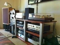
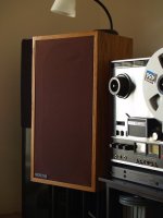
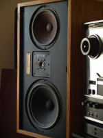
And some with a real camera.
I'm glad to see that Genesis used air core inductors and I would reuse them if I could, but they are so heavily glued onto the terminal board, it's going to be impossible to get them off without breaking them. Not only that, but I would rather just keep the original terminal board and crossover intact just because.
I'm not going crazy on the caps as there's only one, a 10uF on the tweeter (the woofer runs fullrange). For the cap, I'm just going to use a single Dayton PMPC-10 10uF 1% cap.
Now for the question...
It says in the schematic that these inductors are 0.47mH and wound with 22awg wire. Would there be any harm in going with larger 15awg inductors? Since these are on the tweeters, would I benefit from moving up to the foil inductors over the standard 15awg wire inductors? They're only a few bucks more.
As a side note, I'm not going to be incorporating the attenuation switch for the tweeter. With the somewhat plush furnishings, cat tree and carpet in our apartment, the tweeters sound just fine wide open. Then again, I can't tell any difference when I flip the switch either.
One last thing, and this may come a little later down the road, but I was thinking of possibly upgrading to the new aluminum tweeter, but only if there's a real improvement over the 30 year old original phenolic tweeters. Any thoughts on this one?
Many thanks in advance!
Here's an inside pic as well as a quick system pic, both taken by my iPhone and uploaded to my PC automatically via iCloud. A very awesome app I must say! Anywho...
If you look closely, you can see tubes a glowin!
And some with a real camera.
Attachments
It's always wise when replacing coils to not only match the mH value but also the DCR. Going from a 22 ga to a 15 ga will most likely reduce the DCR significantly. One solution is to put a low value resistor in series with the coil to bring the DCR back up to the original value.
It's always wise when replacing coils to not only match the mH value but also the DCR. Going from a 22 ga to a 15 ga will most likely reduce the DCR significantly. One solution is to put a low value resistor in series with the coil to bring the DCR back up to the original value.
What about going with the 18awg Jantzen inductor? It has a DCR of 0.32 ohms. It's the closest thing to the stock 22awg inductor I'm going to find at PE. I want to avoid throwing a resistor in there.
And how can I figure out the DCR value of the stock 22awg 0.47mH inductor?
What about going with the 18awg Jantzen inductor? It has a DCR of 0.32 ohms. It's the closest thing to the stock 22awg inductor I'm going to find at PE. I want to avoid throwing a resistor in there.
And how can I figure out the DCR value of the stock 22awg 0.47mH inductor?
You can get pretty close with an ERSE audio 20 ga air coil @ 0.45 ohms.
or, get a Madisound 22 ga. 0.80 coil and unwind it till it gets to 0.47 mH.
Than again, I have to ask: why are you replacing the coil? If it isn't burnt out, then don't bother. After all, it's just a coil of copper wire.
You can get pretty close with an ERSE audio 20 ga air coil @ 0.45 ohms.
or, get a Madisound 22 ga. 0.80 coil and unwind it till it gets to 0.47 mH.
Than again, I have to ask: why are you replacing the coil? If it isn't burnt out, then don't bother. After all, it's just a coil of copper wire.
How about the Jantzen 20awg 0.45mH? The ERSE you mentioned is 0.441 ohms, the Jantzen is 0.46 ohms. That's probably a bit closer to stock.
The reason(s) I'm replacing the coil is because it is completely glued all over to the terminal board and is wound on a thin plastic, 30+ year old bobbin. It would crumble to pieces before I could get it off the board to reuse. I also want to keep the terminal board/crossover as is in one piece.
Excuse me, but do you really expect to achieve something by changing functioning components in those? Looking at the frontplate and drivers makes me wonder if there's some other substantial issues. I've never heard them anyway...
oh, here's a very good page
"Looking at the front plate and drivers makes me wonder if there's some other substantial issues"
I really doubt that...
I'm very much aware of Huw's site, and these speakers are extremely capable of competing with today's latest offerings.
Last edited:
How about the Jantzen 20awg 0.45mH? The ERSE you mentioned is 0.441 ohms, the Jantzen is 0.46 ohms. That's probably a bit closer to stock.
The reason(s) I'm replacing the coil is because it is completely glued all over to the terminal board and is wound on a thin plastic, 30+ year old bobbin. It would crumble to pieces before I could get it off the board to reuse. I also want to keep the terminal board/crossover as is in one piece.
The Jantzen should work okay. For maximum accuracy to original, the Madisound coil I suggested is the way to go.
The Jantzen should work okay. For maximum accuracy to original, the Madisound coil I suggested is the way to go.
Well which is going to be more crucial, precise mH or DCR?
I have no way of measuring for DCR, so getting the 22awg 0.80mH inductor really wouldn't get me anywhere.
Well which is going to be more crucial, precise mH or DCR?
I have no way of measuring for DCR, so getting the 22awg 0.80mH inductor really wouldn't get me anywhere.
mH is the more critical.
If you into speakers stuff on a regular basis, it's definitely worth investing in an LCR meter. They're not that expensive and you'll get a lot of use out of it.
Google LCR meter and find one in your price range.
mH is the more critical.
If you into speakers stuff on a regular basis, it's definitely worth investing in an LCR meter. They're not that expensive and you'll get a lot of use out of it.
Google LCR meter and find one in your price range.
Thanks for the help Doc.
Yeah, if I get back into the whole speaker building thing and building my own crossovers, I probably should invest in one of those LCR meters.
Also, I put in the order at PE for my goodies. I went a little overboard but figured I'd try something different.
The normal part of the order:
2) Dayton Audio SBPP-SI Binding Post Plate Silver Anodized
2) Dayton Audio BPP-NI Premium Binding Post Pair Nickel
2) Jantzen 0.47mH 18 AWG Air Core Inductors
The "experimental" part of the order:
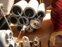
2) Dayton PMPC-6.8 6.8uF 250V Precision Audio Capacitors
2) Jantzen 2.2uF 400V Z-Standard Capacitors
2) Jantzen 1.0uF 800V Z-Superior Capacitors
Yes, I am going to do the controversial act of building a "Cascade Bypass" using three smaller value caps to create the 10uF needed, such as what North Creek Music talks about on their site.
Will it be a waste of money and time? Maybe, maybe not. If it works out for the better, I'll be very happy. If it doesn't, I'll just buy some 10uF caps and be done with it and use these caps elsewhere. It's only a little bit more than what I would have spent on just the two 10uF caps alone.
Gonna go put my flame retardant suit on now.
Yes, I am going to do the controversial act of building a "Cascade Bypass" using three smaller value caps to create the 10uF needed, such as what North Creek Music talks about on their site.
I do that a lot, even with coils, because I'm forever experimenting and most of the time I don't have exact values on hand. I doubt you'll be displeased, or even aware of a difference strapping caps together to get a value.
I have a 60hz hpf somewhere around here for an 8ohm main that's a bundle of caps half the size of a fist and audibly it's just as good as others I have that are single caps. *shrug*
Peter Snell and the makers of Kindel Phantoms were infamous 'bundlers'.
I think PS did it more for convenience to save on having numerous odd-value caps in stock. His much hearalded Model A crossover had numerous bundles of NPE's, most of which consisted of 4 uF values and an odd one or two to make up the total he needed with the whole bundle sitting on a single nano-farad ceramic disk (bypass?) capacitor that anchored the whole schebang to the crossover board with lots of glue.
Below is a pic of the Phantom model xover. There one bundle in there stacked 4 high! The pic on the right is a close up of one of Snell's bundles.
Attachments
Last edited:
Well, we'll see what happens. I'm hoping I'll like the sound and that it will open up these wonderful tweeters just a tad bit more. With a lot of program material, they do tend to be just a little laid back. I feel as though I'm missing that last little bit of the music. Maybe this will regain that in a tasteful way while still remaining nice and smooth.
I'll also be upgrading the wiring at the same time, even though I didn't mention that until just now.
I'll also be upgrading the wiring at the same time, even though I didn't mention that until just now.
Well, we'll see what happens. I'm hoping I'll like the sound and that it will open up these wonderful tweeters just a tad bit more. With a lot of program material, they do tend to be just a little laid back. I feel as though I'm missing that last little bit of the music. Maybe this will regain that in a tasteful way while still remaining nice and smooth.
I'll also be upgrading the wiring at the same time, even though I didn't mention that until just now.
Just to give you something else to think about.....
Recapping WILL open up the sound IF the old cap's ESR has drifted upward.
Another thing to consider is the speaker may not be well balanced for your room. If there are no treble adjustments on the back of the speaker, you should consider reducing the value of any resistor/s in series with the tweeter. For example; if you find there is a 2.5 ohm resistor in series with the tweeter, replace it with a 2 ohm resistor. This will boost the tweeter's output, brightening things up a bit and improving overall imaging.
There is a resistor, but it's connected to the attenuation switch on the back which I have bypassed along with a small 10uF electrolytic. When I do the mods to these speakers, I will not be including this feature.
Since these tweeters are so closely matched to the woofers as far as efficiency is concerned, I don't think these will end up being too bright or anything. And like I said, we have plush couches, carpet, an area rub on top of that, and a large carpeted cat tree.
Well I got one of the speakers done, the right one. I've had it playing now for the past 30 minutes or so while I've been uploading the pics and eating my dinner.
As far as I can tell already, it has a little punchier, tighter bass impact, and this speaker has no wall corner to help it. That of course has to be due to the new 16awg wire I'm using. The upper mids and treble are definitely "airier" and still smooth. I think I've read somewhere that those two different Jantzen caps I'm using take a couple weeks or so to finally settle down. So it'll be interesting to see how they sound a month down the road.
I'm about to shut the system down to pull the left speaker apart and overhaul it. It'll go much quicker since I know what to do now, and the crossover is already assembled.
I'll write more later, but here's a few "teaser" pics to get ya by...
- Status
- This old topic is closed. If you want to reopen this topic, contact a moderator using the "Report Post" button.
- Home
- Loudspeakers
- Multi-Way
- Question about upgrading crossover components...