I have been talking with a well known speaker designer consultant about the design of my next speaker, and began realizing that mine, maybe many others understanding of baffle step compensation is very limited. I thought I would share what he taught me, as it was, at least for me, a new way to do baffle step, and reduces the parts count quite a bit. This also explains why so many crossovers I have seen do not include the normal RL filter for baffle step compensation, but still have a flat response.
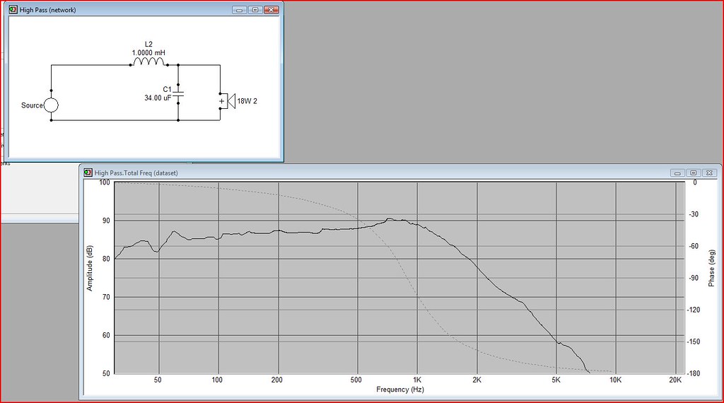
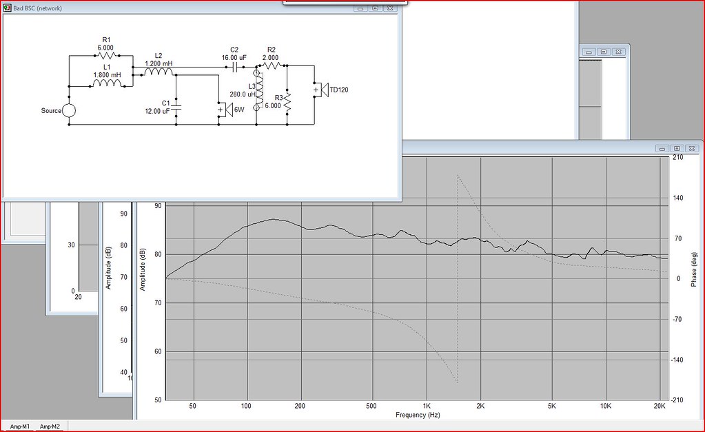
this is a traditional crossover with no bsc, and you can see the normal baffle step problem. In fact, because it was measured on a quasi-IEC infinite bafle, its not even showing all of the baffle step you would get with say a 10" wide enclosure.
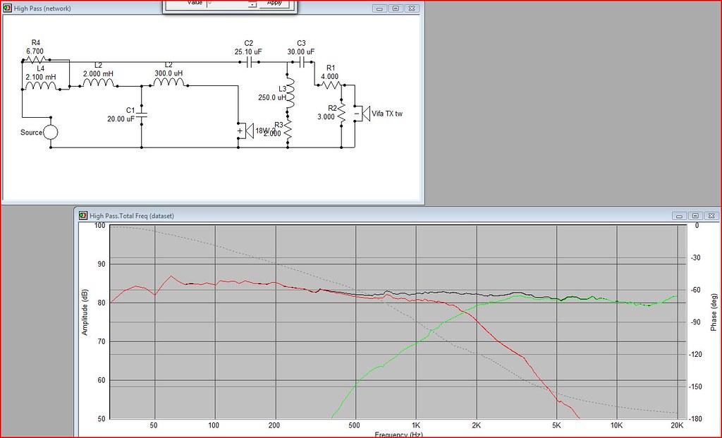
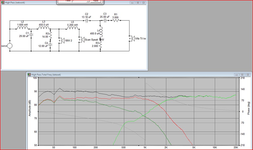
Here is a traditional RL bsc circuit correctly inserted into the crossover. Of course, other values were changed for a flat response. Also, this includes a tweeter, which the other did not.
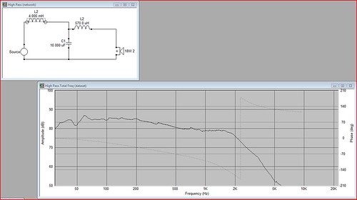
Here is the method I was shown for BSC, without a tweeter, for comparison. The difference is no BSC inductor infront with a resistor, but instead, with the first inductor enlarged considerably. I believe this is essentially cascaded crossovers with a 6db at roughly 500hz and then another at 1.5khz at 12db per octave, making for 18db per octave, 3rd order, at the crossover frequency.
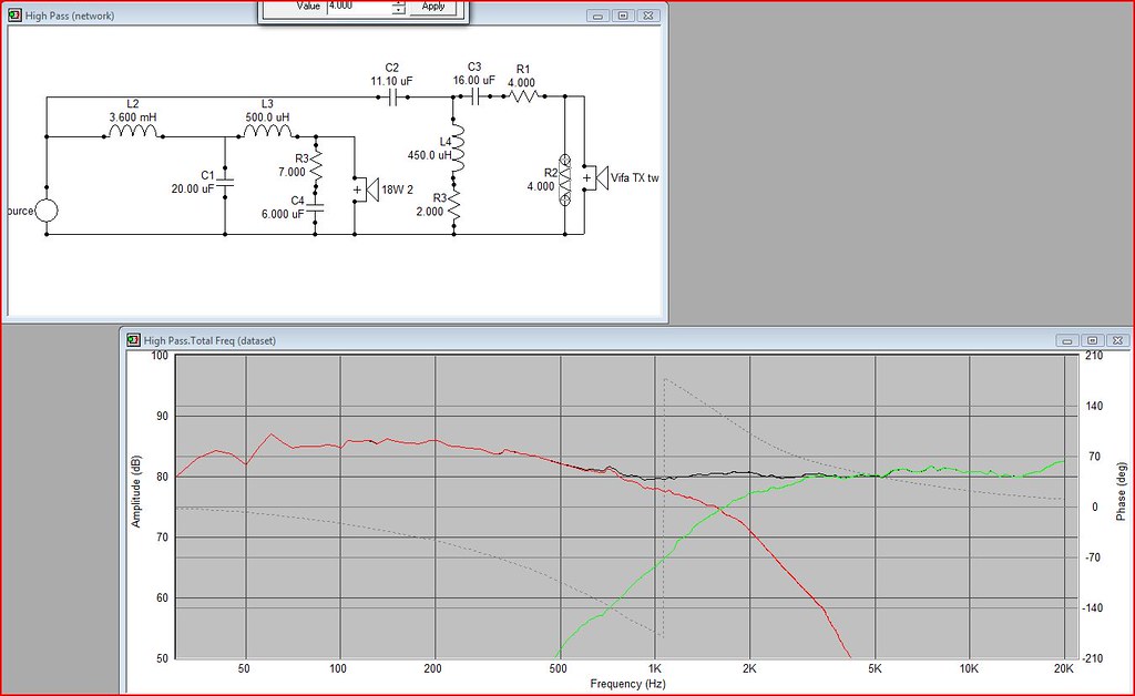
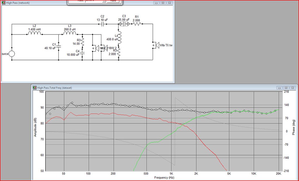
This is the new version with zobel and tweeter added, all modified for a flat response. Not perfect, but I threw it together for examples.
Someone once told me that the BSC circuit should be placed in the tweeters signal path, just FYI, that is not so, and will actually create problems. Again, this came from this well known designer, who I will keep nameless because he didn't give me express permission to credit him with this. He told me this method is nothing new, its what many proper designers use, but he didn't see it among the DIY, for whatever reason.
Ok here is where things got interesting for me. I was wanting to use a 2.5 way bsc design. I had read numerous articles and thought, well its a naturally bsc design, why not, its great. I asked about it, read up, and then began this email conversation with the designer. He said, hey wait, no no no. The inductor, he points out, that is on that .5 woofer has to be huge, which will cause a lot larger phase shift and more distortion. It's also more expensive by quite a bit. However, if you use 2 woofers covering the same range, the impedance halves, and the inductor value can be decreased by half. As is shown below.
The only drawback he pointed out was that the woofers need to be of equal distance to the tweeter. really what he was saying was that the distance needs to be less than the wavelength of the crossover point. This mens that, as in a 6.5" midbass, if placed one below the other, then it must be below 1.8khz. One common solution is the MTM configuration, though some don't like its effect on vertical dispersion (Because vertical dispersion is a good thing?).
I know this is a long post, and I may not be stating everything correctly, or even telling you anything new, but it was a revelation for me. I figured it was worth sharing and discussing.
this is a traditional crossover with no bsc, and you can see the normal baffle step problem. In fact, because it was measured on a quasi-IEC infinite bafle, its not even showing all of the baffle step you would get with say a 10" wide enclosure.
Here is a traditional RL bsc circuit correctly inserted into the crossover. Of course, other values were changed for a flat response. Also, this includes a tweeter, which the other did not.
Here is the method I was shown for BSC, without a tweeter, for comparison. The difference is no BSC inductor infront with a resistor, but instead, with the first inductor enlarged considerably. I believe this is essentially cascaded crossovers with a 6db at roughly 500hz and then another at 1.5khz at 12db per octave, making for 18db per octave, 3rd order, at the crossover frequency.
This is the new version with zobel and tweeter added, all modified for a flat response. Not perfect, but I threw it together for examples.
Someone once told me that the BSC circuit should be placed in the tweeters signal path, just FYI, that is not so, and will actually create problems. Again, this came from this well known designer, who I will keep nameless because he didn't give me express permission to credit him with this. He told me this method is nothing new, its what many proper designers use, but he didn't see it among the DIY, for whatever reason.
Ok here is where things got interesting for me. I was wanting to use a 2.5 way bsc design. I had read numerous articles and thought, well its a naturally bsc design, why not, its great. I asked about it, read up, and then began this email conversation with the designer. He said, hey wait, no no no. The inductor, he points out, that is on that .5 woofer has to be huge, which will cause a lot larger phase shift and more distortion. It's also more expensive by quite a bit. However, if you use 2 woofers covering the same range, the impedance halves, and the inductor value can be decreased by half. As is shown below.
The only drawback he pointed out was that the woofers need to be of equal distance to the tweeter. really what he was saying was that the distance needs to be less than the wavelength of the crossover point. This mens that, as in a 6.5" midbass, if placed one below the other, then it must be below 1.8khz. One common solution is the MTM configuration, though some don't like its effect on vertical dispersion (Because vertical dispersion is a good thing?).
I know this is a long post, and I may not be stating everything correctly, or even telling you anything new, but it was a revelation for me. I figured it was worth sharing and discussing.
For some reason the cascaded filter topologies were downplayed in the 70's. Perhaps because they were not understood well enough. But it makes a lot of sense in this application. The two driver solution makes sense to reduce crossover part cost and you are also getting some gain there by having two drivers. So the baffle step will not be causing as much total loss of sensitivity I believe.
I still think the Elsinore approach is the most elegant way to deal with BSC but it requires four mid/bass drivers.
Thanks pj, good information.
I still think the Elsinore approach is the most elegant way to deal with BSC but it requires four mid/bass drivers.
Thanks pj, good information.
Except for people who don't have XO design software I have never seen anyone actually use a separate circuit for the baffle step.
Any speaker design methodology is a series of tradeoffs. There is no perfect approach.
For example, an MMT, having both woofers covering the same frequency range is problematic because of the lobing issues you will have unless you go with a low XO frequency as you mentioned. This means steep slopes and a limited choice of tweeters that will sound good crossed at 1.8 kHz. An MTM will get around this but then you have the additional issues of trying to get a good power response vs a 2 way.
Regarding the comment that a big inductor causes more phase shift this just isn't true. The phase shift is caused by the acoustic rolloff, not the electrical rolloff or the size of the components causing the rolloff.
The best way to do the .5 way XO is to use a cascaded XO which AFAIK was first introduced to DIY by Jeff Bagby. In this case you design the crossover for the non .5 way driver with no BSC but the proper rolloffs needed to mate with the tweeter. Then you cascade the .5 way BSC XO off the driver side of the other woofer XO. This way you get the BSC from the .5 way section of the XO but then it transitions to the steeper slope of the other woofer as it goes higher in frequency. This minimizes the parts counts as opposed to designing the additional rolloff needed for the .5 way woofer into a seperate XO for the .5 way driver.
Regards,
Dennis
biamping, with a 6dB passive line level xover is a good way to go;
all you need to do is adjust the woofer level and BSC is solved...
all you need to do is adjust the woofer level and BSC is solved...
PeteMcK said:biamping, with a 6dB passive line level xover is a good way to go;
all you need to do is adjust the woofer level and BSC is solved...
surely this is only true if your baffle width matches your woofer XO frequency?
GR Koonce has an excellent discussion of MTM and other configurations in the current AudioXpress. Vertical dispersion is a problem all multi-way speakers deal with. As GR discovers, coaxial/triaxial is not a solution.
Ow. That's complicated.... 😕
We start with a normal 2nd order LP, then go to a 3rd order + separate BSC + tweeter, then to what might be a staggered 2nd order, then to 2nd order with Zobel on woofer and tweeter and so on. Easy to get lost.
Would it be easier to consider only the woofer section?
Does 2nd order with staggered inductor values = 2nd order with BSC?
Hi,
Oversizing the first inductor is the "standard" way of doing it.
A 2.5 way and a 2 way are not the same thing. A 2 way MTM
will have a half value "oversized" inductor but it needs to handle
twice the current so there is no cost saving to be had.
A 2.5 way does not have the c/o point issues of an MTM, and can
be built as a TMM (as can a 2-way, but not often). 2.5 way ties
you into 6dB of compensation, which is inflexible, but if its done
right the advantages outweigh the cost of the "large" inductor.
Well he obviously does not like 2.5 ways, so why not say so.
Its just knocking them, it is the way to do it, it is not wrong.
The 2.5 way can be a cascaded topology as mentioned,
with the 0.5 way inductor after the c/o components.
There is no reason to put a BSC circuit in the tweeter path, not
doing this is not "credit" worthy, its obvious. The only time this
happens is adding an external RL circuit to an unBSC'd speaker.
🙂/sreten.
Oversizing the first inductor is the "standard" way of doing it.
A 2.5 way and a 2 way are not the same thing. A 2 way MTM
will have a half value "oversized" inductor but it needs to handle
twice the current so there is no cost saving to be had.
A 2.5 way does not have the c/o point issues of an MTM, and can
be built as a TMM (as can a 2-way, but not often). 2.5 way ties
you into 6dB of compensation, which is inflexible, but if its done
right the advantages outweigh the cost of the "large" inductor.
He said, hey wait, no no no.
Well he obviously does not like 2.5 ways, so why not say so.
Its just knocking them, it is the way to do it, it is not wrong.
The 2.5 way can be a cascaded topology as mentioned,
with the 0.5 way inductor after the c/o components.
There is no reason to put a BSC circuit in the tweeter path, not
doing this is not "credit" worthy, its obvious. The only time this
happens is adding an external RL circuit to an unBSC'd speaker.
🙂/sreten.
Well as I said, it was all news to me. I mean, if you look up BSC on the internet, this method doesn't show up ever. Instead, you find article after article on BS and Baffle Diffraction, with talk of an RL contour filter as the standard method. They all use an inductor and resistor.
Yes he does not like 2.5 ways, that is true. He gave me his reason for the bias, the large inductor needed, increased distortion in that woofer, he claims poor integration off axis if not correctly placed, etc. I asked if he preferred a true 3 way to a 2.5 way, and he said yes, that is his preference.
Sreten, I wouldn't say that the 2.5 way is THE way to do it, its A way to do it. What I think I'm saying here, what he was saying, is that there are many ways to do it, and each has its advantages and disadvantages.
As for placing the BSC in the tweeter path, I understand its just plain wrong, but I've seen it done. Not only on posted designs on this forum, but also on others. The home theater forums are the most common place I see this done. Not because they are adding it after the fact, but because they designing based on misconceptions.
Hi,
Your post read as though 2.5 ways are wrong. They are not.
The way to do a 2.5 way is not to turn it into a 2 way MTM.
The choice between 2.5 and 2 way is a design choice.
🙂/sreten.
http://www.rjbaudio.com/Audiofiles/FRDtools.html
http://www.geocities.com/woove99/Spkrbldg/
http://www.zaphaudio.com/
http://www.rjbaudio.com/projects.html
http://www.troelsgravesen.dk/Diy_Loudspeaker_Projects.htm
http://www.humblehomemadehifi.com/
http://htguide.com/forum/forumdisplay.php4?f=39
pjpoes said:
Yes he does not like 2.5 ways, that is true. He gave me his reason for the bias, the large inductor needed, increased distortion in that woofer, he claims poor integration off axis if not correctly placed, etc. I asked if he preferred a true 3 way to a 2.5 way, and he said yes, that is his preference.
I don't understand why he would think there would be increased distortion in the .5 way woofer compared to a 2 way or an mtm. The .5 woofer and the other woofer are both playing full range in the low frequencies, just the same way it would be in an MTM. or an mmt with both woofers playing the same frequencies. If he is comparing the 2.5 way to a 3 way with a larger woofer, then yes, it is possible that the smaller woofers of the MTM/MMT will be working harder to play the low stuff
pjpoes said:
As for placing the BSC in the tweeter path, I understand its just plain wrong, but I've seen it done. Not only on posted designs on this forum, but also on others. The home theater forums are the most common place I see this done. Not because they are adding it after the fact, but because they designing based on misconceptions.
I would like to see an example of one of these, can you provide a link?
Thanks and regards,
Dennis
The increased distortion he cites came from the increased distortion caused by the large inductor. The distortion isn't from the speakers being over taxed, its in the inherent reaction of inductance on a signal.
Here is an example that was emailed to me when I was looking for some crossover idea's for the Focal drivers I had. I didn't yet have measurements of these drivers, but was curious to see what had been done, other than Focals own, as well as the French designers of Orca, who follow a similar Montra to Focal.
Orca also has a published design which has another example of an uncommon (I won't say wrong here as they gave me their reasons) BSC method. It's still the LR method, but placed as the last component in the midbass crossover. They told me this can only be done with drivers that have a flat BL curve and low inductance. I tend to question, if it works better as the first component in the midbass crossover, why not just place it there? Ah well, its not that important.
Any other techniques you all care to pass along which help to reduce the component count in a crossover while maintaining good integration and steep slopes? I mean, the more crossovers I build and test, the more I see the advantages and disadvantages of different slopes. I'm finding that for movies, the very steep slopes allow for more natural sound at higher levels, and less noticeable compression distortion. However, for music, I find the shallow slopes sound more natural and throw a deeper, more realistic soundstage. I also noticed that shallower slopes, even 2nd order slopes don't integrate as well off axis at say 1-1.5 meters.
I'm in the process of collecting the necessary parts to construct three different crossovers for the focal towers I made, to do some listening comparisons, as well as measurements. The first will be a 3rd order symetrical design at 1.5khz with an LR filter for BSC. The second will be an asymetrical 2nd/3rd order using the oversized first inductor method, and the last will be using an alternative method he asked me not to share. I can share the graphs I'm sure, just not the schematic. He said its a patented design he uses for his company, and is actually only useful in normal 2 driver 2-way designs like these towers or a small bookshelf. I may construct a 4th using 4th order slopes and a higher crossover of 3khz with the necessary notch filters to tame the cone breakup in that region, along with the oversized first inductor. We will have to see if I have the necessary parts or can get them cheaply, as 4th order designs often require larger value caps and have increased cost.
Sorry if I confused anyone into thinking 2.5ways are wrong, or that I even feel that way. This is the bias of the person I have been talking with. As for the 2-way/2.5/3-way discussion, this was all in discussing the best way to crossover multiples of the same woofer. For instance if I had 4x Dayton 7" reference woofers, what to do with them. You could wire them all up in a parallel series configuration, you could wire them up in two sets of parallel drivers in a 2.5 way, and you could wire them up as a 3 way. His preference was to a 3-way since a 2-way would require a very low crossover point which most tweeters couldn't handle. He prefers the 3-way to a 2.5 way because he likes an MTMMM over a TMMMM because of his perceived better dispersion (I know this is a highly debated topic). None the less, I fully recognize that a 2.5 way is a perflectly acceptable, propper, and even common way of designing a crossover. It's my preferred method for MTM center channels (I think it sounds better than a normal 2 way).
pjpoes said:The increased distortion he cites came from the increased distortion caused by the large inductor. The distortion isn't from the speakers being over taxed, its in the inherent reaction of inductance on a signal.
Unless the inductor is driven to saturation (which wouldn't happen with the proper choice of the wire guage) there should be no additional distortion from a large value inductor vs a smaller one. If you/he are talking about the phase distortion you mentioned previously, this just isn't true. Loudspeaker drivers and the associated XOs (with some exceptions) are minimum phase devices which means that any change in the phase maps to a direct change in the frequency response. In fact with just a first order acoustic low pass on the .5 way driver, you have the least amount of phase shift of any XO type.
Originally posted by pjpoes Here is an example that was emailed to me when I was looking for some crossover idea's for the Focal drivers I had. I didn't yet have measurements of these drivers, but was curious to see what had been done, other than Focals own, as well as the French designers of Orca, who follow a similar Montra to Focal.
Orca also has a published design which has another example of an uncommon (I won't say wrong here as they gave me their reasons) BSC method. It's still the LR method, but placed as the last component in the midbass crossover. They told me this can only be done with drivers that have a flat BL curve and low inductance. I tend to question, if it works better as the first component in the midbass crossover, why not just place it there? Ah well, its not that important.
[/B]
I modeled the Orca XO you posted and the impact of L1 on the tweeter transfer function is minimal as at higher frequencies the transfer function is dominated by R1. So while this approach certainly works in this case, I personally don't see the need to do it this way at least for this XO. Without seeing the actual driver responses combined with the XO it is tough to say for sure though.
You mention placing the BSC circuit at different points in the XO. This can be done to change the shape of the overall shape of the transfer function. This is no different than placing the padding resistor in a tweeter circuit as the first element in the circuit or the last, each resulting a minor change in the frequency response and the damping of the circuit. Again this is just one more way to contour the output of the system to match your targets. All have pros and cons, just like all of the things we have been talking about.
Regards,
Dennis
Hi,
It is true a 2.5/3.5 way inductor is not going to be cheap.
As for not sharing a patented crossover topology .......
I think we are entering the BS zone .......
It is in the public domain, allegedly .......
🙂/sreten.
It is true a 2.5/3.5 way inductor is not going to be cheap.
As for not sharing a patented crossover topology .......
I think we are entering the BS zone .......
It is in the public domain, allegedly .......
🙂/sreten.
By in the public domain, do you mean that I have it? I dont know, I get comments like this from companies all the time. I was asking about methods for shielding cables and was given some good ideas by a cable manufacturer, but was asked not to share it on the Forums because it was patented. I think they gave me the information in the first place because I have purchased from them before. Maybe its patent pending and thats why he doesn't want it shared? I dont know, but I will respect what he said.
Hmm, this looks familiar,
This is exactly how this kind of compensation has been done for decades. I've did it a lot myself back in the eightees when no one has ever heard of the term "baffle step compensation", instead it was used for the compensation for the "rising response" of typical loudspeaker drivers, just another way of looking at the same problem. Funny thing though is that with the change of term used for the problem there was also a change in the way people look at it.
Back then we where looking at the midrange wich rises, today everyone is looking the other way around, they look at the bass response wich decreases. It seems that in our minds these two things are not the same, while in fact they are, and we create different kinds of solutions for it. Very amazing how the human brain works.
- Status
- Not open for further replies.
- Home
- Loudspeakers
- Multi-Way
- Alternative methods for BSC (discussion encouraged)