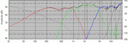
This is my first attempt at designing my own crossover. It's pretty horrible, but honestly, I don't know what I'm doing. This is an attempt at teaching myself what to do. It's a theoretical build on a system I'd love to put in my car someday parents, money, and time permitting. I'd love to have suggestions on what I should be doing differently.
I'm using the Dayton Reference RS225-4, the Dayton Reference RS52AN, and the Tang Band 1166SJ as my model drivers.
Here is a picture of the crossover.
I'm using the Dayton Reference RS225-4, the Dayton Reference RS52AN, and the Tang Band 1166SJ as my model drivers.
Here is a picture of the crossover.
Attachments
I'm looking for advice on what I should be doing, how to go about arranging my crossover, and most importantly, why it should be done. I've tried reading tutorials online, but most of them stop with the basic textbook crossovers. Very little is taught about what to do to tweak the design. Sorry if this seems a bit basic, but I learn best when I can ask questions on things I don't understand (can't really do that on a published web article). Thanks for any advice.
http://www.rjbaudio.com/Audiofiles/FRDtools.html
http://www.geocities.com/woove99/Spkrbldg/
http://www.zaphaudio.com/
http://www.rjbaudio.com/projects.html
http://www.troelsgravesen.dk/Diy_Loudspeaker_Projects.htm
http://www.humblehomemadehifi.com/
http://htguide.com/forum/forumdisplay.php4?f=39
also take note of : http://www.zaphaudio.com/ZDT3.html
 /sreten.
http://www.geocities.com/woove99/Spkrbldg/
http://www.zaphaudio.com/
http://www.rjbaudio.com/projects.html
http://www.troelsgravesen.dk/Diy_Loudspeaker_Projects.htm
http://www.humblehomemadehifi.com/
http://htguide.com/forum/forumdisplay.php4?f=39
also take note of : http://www.zaphaudio.com/ZDT3.html
tinitus said:
I dont understand why you have 12uf before series inductor on mid lowpass
Hi, because he has not simmed the amplifier melting input impedance,
sreten said:
Hi, because he has not simmed the amplifier melting input impedance,/sreten.
Smoke on the water.... Ouch... Nice not so little capacitive load directly on the output of the amplifier.. I seriously doubt any car amplifier would survive long with that load connected to it.
I understand the want to learn how to build a crossover.
But, Since you are putting this in a car why not just go active.
Are you planning on running a subwoofer also?
Because if you aren't a lot of good headunits (which you probably already own) will do a 3-Way system pretty nicely.
In my car I have a fully active 3-way system. It is nice to be able to tune delay and change things on the fly.
Just my $0.02.
sreten said:
Hi, because he has not simmed the amplifier melting input impedance,/sreten.
Guys, that's why he's asking.
Lightwavedude:
What they're talking about is that you have 2 capacitors on the midrange that would cause the amplifier to see a short at some high frequency (coupla khz).
This will kill many MANY amps.
On the woofer, I take it Cz1 and Rz1 are for impedance compensation? If so, Cz1 is way too small, 10pF is a negligible capacitance. 10-100 uF range is more appropriate.
I would omit the woofer resistor.
There are a lot of other issues here, including the location of what appears to be a parallel notch filter on the mid. That with the inductor and cap to ground, in parallel, is what's causing the short.
Your phase response is all over the place. Did you pick values, assemble what 'looked good', and then simulate it for as flat an amplitude response you could get? If so, that's not the way to design a crossover. Existing topologies are available to help you get a better performing loudspeaker. You already have the drivers simulated so you just need to plug in some calculated values for a 'normal' crossover, and tweak the values to match the characteristics of the speakers in your simulation.
I'd suggest starting with a tried and true speaker/crossover design, such as one from www.zaphaudio.com, and also some time spent researching. The links sreten gave are good, spend some time reading, looking at various crossovers with various speaker combinations, play around with your software.
A book every speaker builder of any sort should keep on hand is vance dickason's loudspeaker design cookbook. Not just a summary of designs, it has many practical studies, explanation of theory, and other content. I believe the 6th edition is on blowout at www.madisound.com
- Status
- This old topic is closed. If you want to reopen this topic, contact a moderator using the "Report Post" button.
- Home
- Loudspeakers
- Multi-Way
- First Crossover attempt

