restoring a simple Motorola SH12E hifi record player, and a few holes got in the speaker cones while cleaning the cadmium oxide off the frame with a brass brush dremel tip, so i figured i might as well replace them wholesale.
something doesn't line up for me, however, when looking at the specs for the output section. i'm hoping the attached pdf of the schematic works, if not, this one is easily google-able.
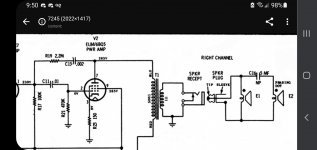
what i am seeing is each 6BQ5 in triode mode, class A, which should mean it wants to see 3500 ohms of load impedance. this schematic shows the impedance ratio of the OPT to be 500:1, so the speaker impedance should be 7 ohms; the standard 8 ohms being even easier of a load to drive.
each speaker measures about 7.3 ohms of DC resistance, indicating they are 8 ohm speakers. but they are wired with two in parallel for each block (one 4", one 6"), which should mean that the total speaker impedance is 4 ohms... right? seems like this would be way too hard of a load for the single 6BQ5.
does the big 5uF cap between the two speakers affect the impedance? that's my best guess, i come from a guitar background and have never seen a cap between different sized speakers like that before.
Philmore # TS60 6.0" Square Flanged Speaker, 8 Ohm 10.0 Watts – MarVac Electronics
thinking this sucker, and its 4" cousin, would do the trick. thoughts?
also actively seeking literature and resources on the belt drives for these units, including how to recognize different styles, and how to maintain them.
something doesn't line up for me, however, when looking at the specs for the output section. i'm hoping the attached pdf of the schematic works, if not, this one is easily google-able.
what i am seeing is each 6BQ5 in triode mode, class A, which should mean it wants to see 3500 ohms of load impedance. this schematic shows the impedance ratio of the OPT to be 500:1, so the speaker impedance should be 7 ohms; the standard 8 ohms being even easier of a load to drive.
each speaker measures about 7.3 ohms of DC resistance, indicating they are 8 ohm speakers. but they are wired with two in parallel for each block (one 4", one 6"), which should mean that the total speaker impedance is 4 ohms... right? seems like this would be way too hard of a load for the single 6BQ5.
does the big 5uF cap between the two speakers affect the impedance? that's my best guess, i come from a guitar background and have never seen a cap between different sized speakers like that before.
Philmore # TS60 6.0" Square Flanged Speaker, 8 Ohm 10.0 Watts – MarVac Electronics
thinking this sucker, and its 4" cousin, would do the trick. thoughts?
also actively seeking literature and resources on the belt drives for these units, including how to recognize different styles, and how to maintain them.
Attachments
A very simple equivalent circuit for a loudspeaker is a resistor in series with an inductor. At low frequencies the impedance of the speaker approaches the value of the resistor, but at higher frequencies the inductance makes the impedance rise to maybe four times or more the nominal impedance at the speakers upper frequency range.
The 5.5µF capacitor in seires with the small speaker is a crossover component, also called a high pass filter, to block low frequencies from getting to the small driver. The combination of an 8Ω driver and 5.5µF capacitor gives a nominal crossover frequency of 3.6kHz. Actually it will be quite a bit lower because of the rising impedance of the small driver due to its own self-inductance, say 2.5kHz. The large driver doesn't have a a complementary low pass filter (which would be a series inductor) because it high frequency rolls off enough naturally.
Below the crossover frequency effectively only the large driver is connected and so the amplifier only sees its impedance alone. Above the crossover the two speakers are effectively in parallel, but both will have impedances well above their nominal 8Ω rating, and the combination is gong to be above 8Ω.
If the replacement Philmore drivers look similar to the originals and will fit the same holes, they should be just fine.
....what i am seeing is each 6BQ5 in triode mode, class A, which should mean it wants to see 3500 ohms of load impedance. .... does the big 5uF cap ...
This is Pentode, NOT triode.
The tube does not "want" a load. The designer selects voltage and current and finds a best-fit on the curves. Yes, for ~~300V on 6BQ5 we often end up at 5k. I do not see "500:1" on the schematic?? (There are DC resistances but this is not audio impedance.)
The speaker on the far side of the capacitor may be neglected because it only comes in above 4KHz where the "8Ohm" woofer is already far over 8 Ohms.
Whatever that does to the tube, is surely fine. Motorola knew their stuff, more than you or me.
The two speakers they selected may have been synergistic, the sum more than the parts. It would be nice if they were not damaged but they are so old that sag and warp may have spoiled their tone.
Running an EL84/6BQ5 single ended at about 300 V is something you don't see often in commercial amplifiers. In this amplifier the anode voltage is 265 V so the voltage between anode and cathode will be a little less than 260 V.
If an EL84/6BQ5 would be run single ended at about 300 V, the primary impedance would probably be chosen higher than 5K unless the designer does not aim for maximum power output. In power pentodes maximum power is obtained when the primary is Vac/Ia. The voltage between anode and cathode will be something like 290 V. Since the maximum anode dissipation of the EL84/6BQ5 is 12 Watt, the anode current should not be higher than 41 mA (P = I x V = 0,041 x 290 = 11,89 W). At these values the primary load for maximum power output will be: Vac/Ia = 290/0.041 = 7073 Ohm.
The schematic does state the impedance of the primary (5000) and of the secondary (10?; it's difficult to make up) of the OPT's.
Last edited:
here's a much better pic of the power section. you can see the indication of the 500:1 impedance ratio on either side of the transformer.
this is fun, learning about crossovers! again, i come from the guitar world where we're spoiled with wiring speakers that are all the same size as each other. thank you for the introduction, especially johnmath! obviously the Motorola was designed well, which is why i want to take this as a learning opportunity with what seems like a very basic hifi circuit. also wanna make sure i'm putting in correct speakers!
the basic idea with the capacitor blocking low frequencies is familiar to me, but i was confused by the size of it! used to seeing much smaller caps used as filters, i thought at 5uF it would have passed all audio frequencies by a long shot. but i guess it's the combination with the heavy loading of the speaker that necessitates the high value...
i found this website for car audio with a simple calculator that seems relevant: Car Audio - Speaker Crossover Chart and Capacitance vs. Frequency Calculator(High-pass) does this seem applicable? the main equation to find the crossover frequency is F=0.159/(C*Rl), which in my case comes out to 0.159/(0.000005*8)=3975, a crossover of about 4kHz. guessing this would be closer to 3kHz by johnmath's estimations, given the rising inductance of the small driver.
using PFL200's equations on the values in this schematic, here's what i arrived at:
Vak(anode-cathode)=256VDC
Ia(max)=12W/256VDC= 46.9mA
max power primary load = 256VDC/46.9mA = 5,458, or about 5,500 ohms. with this OPT, that would mean a 9 ohm speaker for max power transfer. so it seems like both speakers being 8 ohms is accurate. there's no chance i'd have something weird like 10 ohm speakers on this, right?
with the lack of a series inductor for the first driver, it seems as frequency increases, the first driver has fallen off in response enough by the point that the second one starts to respond, that there's a minimum of crosstalk cancellation, right? it seems important in this case, to ensure that a replacement for the large driver has little to no response above 3kHz. or would this be fairly standard among other 8 ohm speakers of this type?
does the impedance of the small driver rise slower than that of the large driver? for example, at 5kHz, can one expect the impedance of the large driver to be substantially larger than that of the small driver? or would they both more likely rise at about the same rate, disregarding any resonant peaks?
here's a much better pic of the power section. you can see the indication of the 500:1 impedance ratio on either side of the transformer....
Please look closely. It says 500Ω and 1Ω. Not 5000 and 10.
The Mullard sheet for EL84 (same tube) shows for 250V supply you may use 5.2k or 4.5k loading to get different harmonic profiles at the same power.
> max power primary load = 256VDC/46.9mA = 5,458, or about 5,500 ohms
That's a useful dart-toss for when you have NO information. The el84/6BQ5 is especially "soft" and wide deviation from V/I give different distortion flavor, not real difference in power output. With zero NFB we would aim to the low side for less sourness at high level.
Attachments
In a nutshell:
* schematic is meant for a repair Tech, not a builder, it shows primary and secondary *wire resistance* which is more useful to him, to check whether windings are not open or shorted which might be *his*concern.
That said, Impedance ratio might also be 500:1, just it´s not a "rule" set in stone.
* the 4" one is not a plain "speaker" but a Tweeter.
Would love to see a picture (from both speakers actually) but tweeter "should" have a closed back frame or be sitting inside its own tiny chamber, even a piece of cardboard tube.
* too late now but rotary brushing away flakey Cadmium plating is a TERRIBLE idea, cadmium is not used for plating any more because it´s a known Cancerigen (sorry) and you are breathing a cloud of tiny particles blown away.
Cadmium | Cancer Trends Progress Report
In a nutshell:
* schematic is meant for a repair Tech, not a builder, it shows primary and secondary *wire resistance* which is more useful to him, to check whether windings are not open or shorted which might be *his*concern.
That said, Impedance ratio might also be 500:1, just it´s not a "rule" set in stone.
* the 4" one is not a plain "speaker" but a Tweeter.
Would love to see a picture (from both speakers actually) but tweeter "should" have a closed back frame or be sitting inside its own tiny chamber, even a piece of cardboard tube.
* too late now but rotary brushing away flakey Cadmium plating is a TERRIBLE idea, cadmium is not used for plating any more because it´s a known Cancerigen (sorry) and you are breathing a cloud of tiny particles blown away.
Cadmium | Cancer Trends Progress Report
All that and more, I say.
Some people, non-techs, don't have a clue about the dangers of cadmium dust, or asbestos for that matter.
They just "dive right in" and have a ball.

In a nutshell:
* schematic is meant for a repair Tech, not a builder, it shows primary and secondary *wire resistance* which is more useful to him, to check whether windings are not open or shorted which might be *his*concern.
That said, Impedance ratio might also be 500:1, just it´s not a "rule" set in stone.
* the 4" one is not a plain "speaker" but a Tweeter.
Would love to see a picture (from both speakers actually) but tweeter "should" have a closed back frame or be sitting inside its own tiny chamber, even a piece of cardboard tube.
* too late now but rotary brushing away flakey Cadmium plating is a TERRIBLE idea, cadmium is not used for plating any more because it´s a known Cancerigen (sorry) and you are breathing a cloud of tiny particles blown away.
Cadmium | Cancer Trends Progress Report
well that's a big part of my issue! i was assuming that was the impedance ratio because i wasn't thinking about the inent for use of a schematic. in that case, this schematic doesn't really give us enough information to derive the winding ratio or impedance ratio, does it?
actually, the 4" speaker has more similar construction to the 6" one, including an open back frame. i'll send pics later.
well aware of the dangers of cadmium oxide, which is why i did it outside, with a strong box fan blowing the dust away from me, while wearing a carbon filter neoprene mask, and holding my breath for each burst of brushing, and a few seconds after. i also only used the brush after getting the first (and most easily persuaded to be airborne) layer off with an air compressor, and then some scrubbing with 409.
i'm not a very experienced tech/designer/anything yet lol, but i'm certainly not tryna die doing this stuff! i understand cadmium oxide is something encountered in various levels while restoring or working on a lot of vintage electronics, so i am all ears for the real veterans' approach to safety here! i've done lots of research and found many different approaches. definitely seen some folks say they won't work on anything that has a visible coating of it, seems very limiting in terms of what you can work on but abstinence is the best protection! i do think i will try to solve this issue more chemically with the next project, though. ones i've seen get a lot of support are mineral spirits, and mother's mag & aluminum polish.
Some drivers are made to be wide range with extended high frequency response by the addition of a smaller center mounted 'whizzer' cone inside the main cone, for example. Choose a bass driver with a cone material and construction that looks similar to the one you have.with the lack of a series inductor for the first driver, it seems as frequency increases, the first driver has fallen off in response enough by the point that the second one starts to respond, that there's a minimum of crosstalk cancellation, right? it seems important in this case, to ensure that a replacement for the large driver has little to no response above 3kHz. or would this be fairly standard among other 8 ohm speakers of this type?
does the impedance of the small driver rise slower than that of the large driver? for example, at 5kHz, can one expect the impedance of the large driver to be substantially larger than that of the small driver? or would they both more likely rise at about the same rate, disregarding any resonant peaks?
The impedance rise with frequency of the larger driver will be greater than the smaller one, because it's larger voice coil will have more inductance.
Well, resistance ratio is a clue, so not that bad.well that's a big part of my issue! i was assuming that was the impedance ratio because i wasn't thinking about the inent for use of a schematic. in that case, this schematic doesn't really give us enough information to derive the winding ratio or impedance ratio, does it?
2 options:
1) search for a similar amp schemating, basically same tube and roughly same +V , see what they use
Maybe some datasheet example applies too.
2) if OT works but you have speaker doubts, feed 1kHz into amp, drive it to clipping, in SE amps proper impedance shows roughly symmetrical clipping, mismatching shows premature top or bottom clipping.
Try higher or lower until you find optimum.
No need for OCD, the keyword here is roughly
I have seen similar horrors back in the dayactually, the 4" speaker has more similar construction to the 6" one, including an open back frame. i'll send pics later.
, guess the "cabinet" is basically open back (perforated hardboard back or similar), because in a closed (or reflex) cabinet woofer mercilessly pushes small cone without asking, if it´s not isolated.Oh well.
HAPPYwell aware of the dangers of cadmium oxide, which is why i did it outside, with a strong box fan blowing the dust away from me, while wearing a carbon filter neoprene mask, and holding my breath for each burst of brushing, and a few seconds after. i also only used the brush after getting the first (and most easily persuaded to be airborne) layer off with an air compressor, and then some scrubbing with 409.
you did it that way, I was worried.Lungs self clean of *light* stuff (wood dust, lint, etc.) but heavy metals, glass dust, asbestos, etc. stay forever doing terrible things.
Yes, Cadmium was VERY popular back in the day, repaired TONS of yellow-greenish Japanese chassis, while Germans used very complex Zamak castings.
And perforated hardboard was everywhere, as in Electronics or Cabinet back panels, or bottom panels even in some expensive Electronics. And all B/W tube TVs, of course
Last edited:
> ... guess the "cabinet" is basically open back (perforated hardboard back or similar), because in a closed (or reflex) cabinet woofer mercilessly pushes small cone ...... perforated hardboard was everywhere, as in Electronics or Cabinet back panels, or bottom panels even in some expensive Electronics. And all B/W tube TVs, of course....
Actually this is snap-off speaker pods "for stereo!" The similar things from the late 1960s had plastic/composite cases. However this Motorola's "design" would have been a lot about cost-cutting. Even using-up surplus speaker inventory.
Actually this is snap-off speaker pods "for stereo!" The similar things from the late 1960s had plastic/composite cases. However this Motorola's "design" would have been a lot about cost-cutting. Even using-up surplus speaker inventory.
Attachments
> ... guess the "cabinet" is basically open back (perforated hardboard back or similar), because in a closed (or reflex) cabinet woofer mercilessly pushes small cone ...... perforated hardboard was everywhere, as in Electronics or Cabinet back panels, or bottom panels even in some expensive Electronics. And all B/W tube TVs, of course....
Actually this is snap-off speaker pods "for stereo!" The similar things from the late 1960s had plastic/composite cases. However this Motorola's "design" would have been a lot about cost-cutting. Even using-up surplus speaker inventory.
well that makes me feel a bit better about having ruined them lmao!! yes, the unit gives me the impression overall of being a decent circuit, but the actual construction is pretty cheap - the heater wires were just kinda running willy-nilly across the whole chassis, for example. got them suckers twisted tight!
purchased the Sam's photofact and got some good info. none of these part numbers turn up anything, obviously, but we have listed impedances! guessing "VC" stands for voice coil. definitely confused by the ranges mentioned - are these saying that speakers anywhere between 6-8 ohms of impedance are suitable for the large driver?
as i purchased 8 ohm Philmore speakers for both the 6" and 4" drivers, it seems i might have to search for another 4" driver, likely a 12 ohm one. however, i'm confused by the fact that the 4" driver read the exact same DC resistance as the 6"... given that fact, combined with the insight from PRR that these were likely used to move old inventory... could it be the case that this 4" driver actually is at 8 ohms, and that it's a close enough fudge to their listed 10-12 ohm range that it's not gonna make a detrimental difference?
Attachments
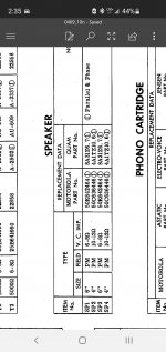
Speaker impedance is not critical.
Buy a speaker these days, it will be far better than Moto's back warehouse stock. Get a nice "full range" six-inch rated 8 Ohms. Block-off the 4" hole and ignore the crossover cap.
Yes indeed.
Keep things simple, take a couple suggestions, and save bandwith.
- Home
- Live Sound
- Instruments and Amps
- Motorola SH12E speaker impedance