Hello esteemed members, I have a fairly general question about the bit of circuitry in the title. I have been on the hunt for a simple active tube mid control like this for a while. Happy to have stumbled onto it.
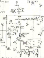
It is pretty similar to the one knob "Garnet" tone control, having a pot connected between plate & cathode, wiper to ground essentially, except in the case of this Ampeg circuit there is an inductor in series with that wiper/ground path. I'm oversimplifying a bit... also, the plate and cathode loads are equal.
Here's my Q: in the Ampeg, signal is taken from the plate for the following stage, but could not this circuit do double duty as a cathodyne phase inverter?
Thanks!
Attachments
No.
Pick one, either use it as a tone control or remove pot and resonant circuit and use it as an inverter.
Hint:
* a PI gives you 2 exact same signals, just out of phase.
* a tone control (or active gain stage) gives you 2 different signals, unless wiper is on "5" in a linear pot.
Pick one, either use it as a tone control or remove pot and resonant circuit and use it as an inverter.
Hint:
* a PI gives you 2 exact same signals, just out of phase.
* a tone control (or active gain stage) gives you 2 different signals, unless wiper is on "5" in a linear pot.
I'm unsure what you mean by that sir. As far as I understand the mid control as it is designed in this Ampeg provides either a cut or boost to the mids when you move the wiper off center, yeah? what is this dip you speak of?
I was just thinking that if I took the signal off the cathode instead, I could couple directly to the next stage's grid. This is not really a big deal though.
I believe what I'll do is build it and see. Also I had better try and look for a chance to play through the original item. I would like to build a version where the switch to adjust the frequency does not jump to such distant frequencies (if the panel labels are to be believed, at least), but instead provides a much more subtle "voicing" adjustment.
A dip is a cut, no? But I said it *all* wrong. Forgive me.
There is no peak/boost at the cathode.
(Duh! It is a cathode follower. Even extreme loads make little change of gain.)
Here's the plots, both ends of the tube, three knob settings. Plate/anode has a lovely +/-8dB boost or cut. Cathode is basically flat, a mere 2dB down when the pot puts the L-C tank directly upon it.
The "1H" is a total guess; a different value works the same but different frequency.
> try and look for a chance to play through the original ..... frequency does not jump to such distant frequencies .... much more subtle "voicing" adjustment.
I maintained a V-40 through dozens of students, some quite brilliant. I do not recall one ever really understanding this network.
Attachments
That makes a lot more sense to me, thank you! Yes, of course the cathode would act this way. Your explanation is quite clear now, and the schema/plot (it's a circuit emulation?) is very very helpful.
My hat is off to you Mr. PRR. I don't chime in much around here but I have observed over the course of many, many years how generous you are with your knowledge. As I often say to my favorite people, "you are a peach among ducks".
My hat is off to you Mr. PRR. I don't chime in much around here but I have observed over the course of many, many years how generous you are with your knowledge. As I often say to my favorite people, "you are a peach among ducks".
the original has a 300mH coil in that middle switch position, which is marked "1kHz" on the front panel. I thought that is pretty close to what I would want, but your 1H looks like it does the right thing too. I think I'll just build something and see. I was thinking to have a rotary switch and a bunch of little inductors to choose from, in series with a ~220mH ...but we shall see.
...a 300mH coil in that middle switch position, which is marked "1kHz"....
The mechanical idiot figures 840Hz, but so broad that in Ampeg's day they would have to obsess to be sure. The real broad curve explains why I sometimes saw this amp's knobs turned every which way and while it was "wrong" it wasn't "bad".
Attachments
I presently use a Walter Woods "electracoustic" amplifier, an engineering marvel and certainly the best amp I have ever owned. I sure don't know what kind of 'Q' it's mid control has, but I do love dialing in a very mild mid boost with my hollowbody archtop. It is very touchy though, a very small tweak to the "frequency" knob makes big changes. Maybe that's the behavior of a narrowish band. It sounds great when you set it up with care, but it also has settings that are definitely "wrong".
So I'm not convinced a narrower band is something I should be interested in... but maybe that could be achieved simply with a higher gm tube. Or, perhaps a gyrator instead of the inductor would be an improvement for this Ampeg circuit, but... I'm trying to overcome my usual OCD, accept that I don't really know what I'm doing, and just build something. Thanks for your input.
So I'm not convinced a narrower band is something I should be interested in... but maybe that could be achieved simply with a higher gm tube. Or, perhaps a gyrator instead of the inductor would be an improvement for this Ampeg circuit, but... I'm trying to overcome my usual OCD, accept that I don't really know what I'm doing, and just build something. Thanks for your input.
That is NOT a cathode follower stage but a regular gain stage, with output taken from the plate and nowhere else.
It has HUGE NFB: cathode resistor same value as plate vresistor, so gain ends up being 1X if unmolested.
LC resonant network either grounds plate to get a dip at resonant frequency or cathode, to get a peak there.
Pot allows getting all intermediate values from peak to dip so providing user flexibility.
In a way, 100% NFB tube is working as a crude Op Amp, go figure.
- Status
- This old topic is closed. If you want to reopen this topic, contact a moderator using the "Report Post" button.
- Home
- Live Sound
- Instruments and Amps
- Ampeg V4 mid control