Hi people,
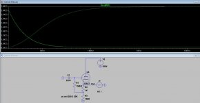
In LTSpice I use the following method to determine output impedance, see pic.
The thing is that if I don't ground the input through a cap, I get unrealistic results. What remains weird to me is the fact that the input caps size determines the slope of the output impedance.
When I don't ground the input and attach a circuit before the input this circuit also shapes the output impedance.
I was under the impression a buffer should isolate the output impedance from the input, why is it related here?
Is my solution of the cap and grounded input correct?
Attachments
> that if I don't ground the input through a cap
Then the infinite-impedance grid "follows" the voltage at the other end of R1, essentially the forcing voltage/current. (Put a Probe on the grid to see this voltage.)
> the input caps size determines the slope of the output impedance. When I don't ground the input and attach a circuit before the input this circuit also shapes the output impedance.
Ditto. The grid follows more or less depending what you connect to it.
What are you going to do in real life? Possibly 0.022uFd to a plate of maybe 40k audio impedance. That cap would be selected to be "negligible" (compared to related circuit impedances) to below the audio band. As your plot shows, 0.022uFd against a Meg is pretty negligible to 10Hz.
Thanks PRR!
Interesting, so it is not a LTSpice error, this actually happends in real life too.
I have a tone stack before the cathode follower, so for every setting I will get a different output impedance slope, cool.
Interesting, so it is not a LTSpice error, this actually happends in real life too.
I have a tone stack before the cathode follower, so for every setting I will get a different output impedance slope, cool.
Your SPICE usage looks correct. Grounding the input is good, too, since a floating node is not allowed.
...I was under the impression a buffer should isolate the output impedance from the input, why is it related here?...
Buffering is never perfect. In critical work we measure transfer both ways, forward and reverse.
A buffer can also be understood to "follow its input". In this (initial) case, by leaving the input open, it doesn't know what to follow. The next best signal the input sees is sneakage through the 1Meg grid resistor from... the output. So ideally the output voltage follows-- the output voltage. This is a high impedance.
Do you actually need a specific output impedance? Normally it is fine to just make it "low enough", and maybe fine-trim with a build-out resistor.
Thank you Egellings and PRR.
PRR I would like to make the output impedance as low as possible. A build-out resistor can only increase the output impedance right?
PRR I would like to make the output impedance as low as possible. A build-out resistor can only increase the output impedance right?
..........I would like to make the output impedance as low as possible.....
That's not a useful goal. There's no natural limit how much resource you can throw in. 600 Ohms? 6 Ohms? 6 milliOhms?? (Each alternator under Hoover Dam is likely 0.001 Ohm under usual regulation.)
600 Ohms is low enough to drive audio wires a hundred miles; and lower is not necessarily better. It will drive a large number of 10K loads with little interaction. If loads may be arbitrarily shorted while the show goes on, in tube-tech you might wish to provision a dedicated triode for each load.
You also have some coupling back to the input via the 1 MΩ resistor. It's small, but not zero. That'll affect the output impedance.
A CCS loaded cathode follower could potentially provide a more constant output impedance. That's worth a quick simulation anyway.
Tom
A CCS loaded cathode follower could potentially provide a more constant output impedance. That's worth a quick simulation anyway.
Tom
You also have some coupling back to the input via the 1 MΩ resistor. It's small, but not zero. That'll affect the output impedance.....
That was his original point: floating input gave odd result. I suspect any input he "should be using" will be about all the same.
If a CSS is legal, why not a NE5532? Lots lower Z with better drive ability.
All-tube, build a 12AX7 plus two 6V6. 8 Ohm tap will deliver line-level and reasonable NFB makes sub-Ohm output Z. Keeps you warm in winter too.
- Home
- Live Sound
- Instruments and Amps
- Is this method of measuring output impedance correct?