For those of you who may be fans of the somewhat rare Randall tube amps of the late 80's, I thought I would share my experience with repairing an RGT 100 HT made in 1989. I purchased the it on eBay as a non-working amp with the intention of repairing and reselling it (although more for the challenge of figuring out what was wrong and fixing it). I apologize in advance for the length of this post, but there is very little information on these amps available on the web so I thought I would share what I found in detail.
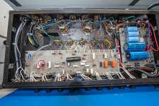
When I received the amp it was in fantastic physical condition, with barely any signs of wear, although it weighed a ton (this is the rack version of the amp). I plugged in the amp and immediately noticed one of the four power tubes red plating. I turned the amp off and removed the outer chassis to get a good look at the tubes (picture of chassis with exposed boards below). Someone had been through the amp boards previously because there are green dot markings next to some components and one of the capacitors on the main board had been replaced (circled in red, left side of photo). Anyway, not only was one of the four 6L6GC's (the one that had red plated) completely clouded at the top, but so was the 12AT7 PI tube (pictures of both tubes below). I removed all four 6L6's and the 12AT7, replaced the 12AT7 and plugged a new 6L6 into the same socket as the red plating 6L6. Both tubes began to red plate. I then moved the power tube to each of the other four sockets and it red plated in each position.
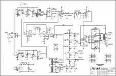
At this point, I realized that something was causing an excessive amount of current to pass through the PI and all the power tubes. My first thought was that there was insufficient quiescent bias on the power tube grids so I looked for a schematic on the web. I only found two versions of the schematic that were extremely difficult to read. So I took the step of redrawing the schematic in Illustrator to make it easier for me to do the troubleshooting. I have attached a copy of the reworked schematic (with permission to recopy for non-commercial purposes). I think it's correct, but it might contain typos so use it at your own risk (I could not determine the value of the cathode resistor for the PI because it wasn’t on the original schematic and I couldn’t accurately trace the path on the PCB – possibly 2.2KΩ).
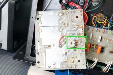
After reviewing the schematic I removed all the tubes and powered up the amp. I checked the plate voltages for the power tubes and the PI and they were all within spec. However, when I checked the grid bias voltage on pin 5 of the power tubes it was essentially zero! This was clearly the source of the red plating problem since the full plate/cathode current was passing through the power tubes in the quiescent state with no negative grid bias – and it was pulling a large current from the plates of the PI through the power tube grids causing the PI to red plate as well. To determine why there was no grid bias voltage, I had to trace the voltage and current through the power board (the small board on the right side of the photo of the underside of the chassis). However, there was no component layout for the power board, so the first step was to create one from the schematic and a physical inspection of the board.
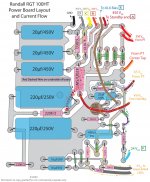
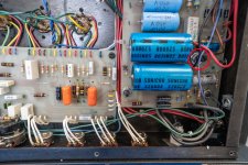
I’ve included my version of the layout below, which also includes dashed lines representing the current flow through the different sections of the power board (the fat dashed curved line in the middle of the layout is a jumper wire on the underside of the power board – see the photo of the underside of the power board below). Interestingly, although the schematic shows two rectifier diodes coming off the PT secondary (red wires) prior to the standby switch, the board actually has two pairs of two rectifier diodes each in series instead. I suspect this was done to raise the peak inverse voltage of the diodes in series. Once I figured out which components were in the circuit providing the bias voltage marked “E” on the schematic (on my Power Board Layout it is the dashed blue line starting at the middle right side of the power board – the red/blue wire labelled as “85Vac From PT” – and passing up through the brown wire at the top of the board, labelled “To 6L6 Bias”). I tested them sequentially for continuity and voltage and discovered the culprit – the current and the voltage stopped at the wiper of the 10KΩ linear trim pot shown in brown in the right center of the layout (circled in red on the photos of the chassis underside and the power board). There was absolutely no voltage at the middle pin of the pot. I tested this conclusion by temporarily jumping a 5.6 KΩ resistor across the entry and wiper terminals of the trim pot, shown on the photo of the underside of the Power Board (green rectangle), and got sufficient voltage and current to each of the pin 5’s of the 6L6’s to stop the red plating.
After unmounting the power board and struggling to manipulate it so that I could get to the underside of the board (causing a few of the hard wired connections to break and need re-soldering) I was finally able to install the new trim pot. There was now voltage and current running to pin 5 of all the power tube sockets. Using a Euro Tubes Bias Probe and the trim pot, I set the 6L6 bias current to about 40 µa (slightly on the warm side) and replaced the two large 220 µf capacitors on the power board (they were slightly out of spec). I also installed the new 12AT7 PI and four new matched 6L6GC’s. I powered up the amp and the sound is fantastic – both channels powerful and clean with the gain low and very powerful and raw with the gain up.
I hope this can be of some use to fellow Randall tube amp owners/repairers.
When I received the amp it was in fantastic physical condition, with barely any signs of wear, although it weighed a ton (this is the rack version of the amp). I plugged in the amp and immediately noticed one of the four power tubes red plating. I turned the amp off and removed the outer chassis to get a good look at the tubes (picture of chassis with exposed boards below). Someone had been through the amp boards previously because there are green dot markings next to some components and one of the capacitors on the main board had been replaced (circled in red, left side of photo). Anyway, not only was one of the four 6L6GC's (the one that had red plated) completely clouded at the top, but so was the 12AT7 PI tube (pictures of both tubes below). I removed all four 6L6's and the 12AT7, replaced the 12AT7 and plugged a new 6L6 into the same socket as the red plating 6L6. Both tubes began to red plate. I then moved the power tube to each of the other four sockets and it red plated in each position.
At this point, I realized that something was causing an excessive amount of current to pass through the PI and all the power tubes. My first thought was that there was insufficient quiescent bias on the power tube grids so I looked for a schematic on the web. I only found two versions of the schematic that were extremely difficult to read. So I took the step of redrawing the schematic in Illustrator to make it easier for me to do the troubleshooting. I have attached a copy of the reworked schematic (with permission to recopy for non-commercial purposes). I think it's correct, but it might contain typos so use it at your own risk (I could not determine the value of the cathode resistor for the PI because it wasn’t on the original schematic and I couldn’t accurately trace the path on the PCB – possibly 2.2KΩ).
After reviewing the schematic I removed all the tubes and powered up the amp. I checked the plate voltages for the power tubes and the PI and they were all within spec. However, when I checked the grid bias voltage on pin 5 of the power tubes it was essentially zero! This was clearly the source of the red plating problem since the full plate/cathode current was passing through the power tubes in the quiescent state with no negative grid bias – and it was pulling a large current from the plates of the PI through the power tube grids causing the PI to red plate as well. To determine why there was no grid bias voltage, I had to trace the voltage and current through the power board (the small board on the right side of the photo of the underside of the chassis). However, there was no component layout for the power board, so the first step was to create one from the schematic and a physical inspection of the board.
I’ve included my version of the layout below, which also includes dashed lines representing the current flow through the different sections of the power board (the fat dashed curved line in the middle of the layout is a jumper wire on the underside of the power board – see the photo of the underside of the power board below). Interestingly, although the schematic shows two rectifier diodes coming off the PT secondary (red wires) prior to the standby switch, the board actually has two pairs of two rectifier diodes each in series instead. I suspect this was done to raise the peak inverse voltage of the diodes in series. Once I figured out which components were in the circuit providing the bias voltage marked “E” on the schematic (on my Power Board Layout it is the dashed blue line starting at the middle right side of the power board – the red/blue wire labelled as “85Vac From PT” – and passing up through the brown wire at the top of the board, labelled “To 6L6 Bias”). I tested them sequentially for continuity and voltage and discovered the culprit – the current and the voltage stopped at the wiper of the 10KΩ linear trim pot shown in brown in the right center of the layout (circled in red on the photos of the chassis underside and the power board). There was absolutely no voltage at the middle pin of the pot. I tested this conclusion by temporarily jumping a 5.6 KΩ resistor across the entry and wiper terminals of the trim pot, shown on the photo of the underside of the Power Board (green rectangle), and got sufficient voltage and current to each of the pin 5’s of the 6L6’s to stop the red plating.
After unmounting the power board and struggling to manipulate it so that I could get to the underside of the board (causing a few of the hard wired connections to break and need re-soldering) I was finally able to install the new trim pot. There was now voltage and current running to pin 5 of all the power tube sockets. Using a Euro Tubes Bias Probe and the trim pot, I set the 6L6 bias current to about 40 µa (slightly on the warm side) and replaced the two large 220 µf capacitors on the power board (they were slightly out of spec). I also installed the new 12AT7 PI and four new matched 6L6GC’s. I powered up the amp and the sound is fantastic – both channels powerful and clean with the gain low and very powerful and raw with the gain up.
I hope this can be of some use to fellow Randall tube amp owners/repairers.
Attachments

I bought Randall RGT 100HT from Craigslist but the reverb is not working I believe it had been replaced (not original one) I bought a new one based on the part number of the current one and it is still not working properly. Can anyone please provide me the correct part number (or similar) of reverb tank if you know of?
Disconnect the tank. Get guitar, cords, and a working mini-PA rig.
Reverb Send should give a very hot "Line Level". It should even drive headphones.
Reverb Return should, like any reverb, buzz big-time if you touch the hot pin with the reverb gain up.
With right end of tank plugged to reverb return, bumping the tank should thunder.
Reverb Send should give a very hot "Line Level". It should even drive headphones.
Reverb Return should, like any reverb, buzz big-time if you touch the hot pin with the reverb gain up.
With right end of tank plugged to reverb return, bumping the tank should thunder.
Thanks for the schematic.
Found it WEIRD that it is exactly same design and structure as the SS one, clipping is SS, so tubes are NOT "doing their thing", at all.
A more expensive way to achieve exact same endresult, and obviously a Marketing decision to catch Tubeheads.
Only difference possible comes in using amp full blast, "all knobs on 10", so power amp provides the main distortion, but at any lower volume ......... forget it.
Also the constant current SS power amp will sound more "brutal" than the Tube one .... which is the main reason for buying a Randall anyway.