Hi there.
A friend brought me a Little Mark Tube for repair.
I've asked questions regarding the PSU there: https://www.diyaudio.com/forums/pow...ailure-ir21531-please-help-3.html#post6156903
But I was advised to start a new thread here since last question is not PSU related.
A faulty cabinet blew 2 output transistors and then the 2 power supply transistors. They were the 4 only parts I've diagnosed faulty and replaced.
The amp is working again 🙂
I've replaced the 6 output MOSFETs with Vgs matched trios.
Now...
Does bias has to be adjusted (via TRIM1 pot and if it's its purpose) and how?
There nothing explained in the service manual. Here it is: https://music-electronics-forum.com/attachment.php?attachmentid=37571&d=1453963798
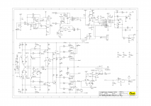
The Little Mark Tube I have shares the same DA510 board. Schematic attached.
I've read on an italian forum that Markbass replied that idle current must be between 40mA and 50mA. But gave no procedure or values. That's all.
Any help would be appreciated 🙂
Thanks!
A friend brought me a Little Mark Tube for repair.
I've asked questions regarding the PSU there: https://www.diyaudio.com/forums/pow...ailure-ir21531-please-help-3.html#post6156903
But I was advised to start a new thread here since last question is not PSU related.
A faulty cabinet blew 2 output transistors and then the 2 power supply transistors. They were the 4 only parts I've diagnosed faulty and replaced.
The amp is working again 🙂
I've replaced the 6 output MOSFETs with Vgs matched trios.
Now...
Does bias has to be adjusted (via TRIM1 pot and if it's its purpose) and how?
There nothing explained in the service manual. Here it is: https://music-electronics-forum.com/attachment.php?attachmentid=37571&d=1453963798
The Little Mark Tube I have shares the same DA510 board. Schematic attached.
I've read on an italian forum that Markbass replied that idle current must be between 40mA and 50mA. But gave no procedure or values. That's all.
Any help would be appreciated 🙂
Thanks!
Attachments
I think you have all the information you need in those two sentences. 🙂Does bias has to be adjusted (via TRIM1 pot and if it's its purpose) and how?
<snip>
...Markbass replied that idle current must be between 40mA and 50mA.
Let's pick the middle value for bias current, 45 mA. This current will be divided equally between the three matched FETs (we hope). That means R29 will have 15 mA flowing through it.
Since R29 = 0.33 ohms, the voltage drop across it (when 15 mA flows through it) will be 5 millivolts.
So now you know how to adust your bias current: Connect a DC voltmeter on a suitable millivolt range between "Source H" and "Out". Adjust TRIM1 until the meter reads 5 mV or 0.005 volts. You're done!
By the way, the bias adjust circuit is very poorly designed. Eventually the TRIM1 potentiometer will get old and scratchy, and the wiper will lose contact with the track. When this happens, T9 will turn off, and the output MOSFETs will start to flow too much current. They will rapidly overheat and burn out.
This can be fixed by a slight change in design. Wire a resistor between base and collector of T9. If the trimpot (TRIM1) goes bad, this resistor will now turn T9 fully on. This will reduce the bias on the output MOSFETs, making them go cold. There will be increased crossover distortion until TRIM1 is fixed, but nothing will burn out.
The value of this additional safety resistor depends on some component details I don't know, including the resistance value of TRIM1. This additional resistor needs to be big enough in value to allow you to still use TRIM1 to adjust the proper output bias current. At the same time, this resistor needs to be small enough in value so that, if TRIM1 goes bad, the output MOSFETs are protected, as described in the previous paragraph.
If you measure the DC voltage across C4, and the DC voltage across R38, and report those two numbers, along with the value of TRIM1, I think I can help you figure out a suitable value for this additional safety resistor.
-Gnobuddy
Last edited:
Whoa. That's a great and very detailed post! 🙂
Once I bring back the baby on the bench. I'll make measurements and report back here. Maybe tomorrow.
Thanks!
Once I bring back the baby on the bench. I'll make measurements and report back here. Maybe tomorrow.
Thanks!
Well. I'm back with some measurements 🙂
I managed to identify accessible probing points for the bias voltage, as no such point has been anticipated in the design, attesting again that it has not been thought as serviceable.
I had to remove again a lot of silicone to get access to them. Every THT component on this board is literally drown in silicone 😡
So I've found R43 and R44 legs to probe "SourceH" and "SourceL" from "Out" (at relay out).
At first power up, I measured 10mV climbing slowly and stabilizing to 16mV as the unit was warming up. Then, before I've had the chance to write that down, the voltage started to climb to 33mV, then decreased back to 16mV then went all over the place in a matter of seconds as far as 100mV 😱 The protection circuit triggered and the relay disengaged almost at the same time I was powering down the unit.
I've brought back the unit on, this time with a DBT. The 80W bulb clearly limits the current as 80V rails are measured at 55V.
With the DBT, I've measured 6mV bias voltage at SourceH 🙁
A mere touch to the multiturn trimpot brought it immediately to 4mV (was the wiper contact loose on the track?).
I've decreased it by a few turns to 2,5mV for safety.
Back on without the DBT, now SourceH-Out bias climbs to 6,3mV cold then slowly decreases to 5mV stays steady after 3 minutes warming up. I have measured after warm up:
The heatsinks become quickly warm to the touch, the one on the negative side (which also the exhaust fan side) and has 0,5mV less bias is a little cooler than the other.
Don't know if the bias has to be set cold or warm.
Unless advised against that, I'll now let the unit run on the bench and verify that everything stays OK.
By the way, T9 is a SMD transistor. I'm not sure I have skills to solder anything there 🙄
But I'd rather try to implement the additional protection you suggest as it seems that the bad scenario you predicted already happened.
Many thanks for your help 🙂
I managed to identify accessible probing points for the bias voltage, as no such point has been anticipated in the design, attesting again that it has not been thought as serviceable.
I had to remove again a lot of silicone to get access to them. Every THT component on this board is literally drown in silicone 😡
So I've found R43 and R44 legs to probe "SourceH" and "SourceL" from "Out" (at relay out).
At first power up, I measured 10mV climbing slowly and stabilizing to 16mV as the unit was warming up. Then, before I've had the chance to write that down, the voltage started to climb to 33mV, then decreased back to 16mV then went all over the place in a matter of seconds as far as 100mV 😱 The protection circuit triggered and the relay disengaged almost at the same time I was powering down the unit.
I've brought back the unit on, this time with a DBT. The 80W bulb clearly limits the current as 80V rails are measured at 55V.
With the DBT, I've measured 6mV bias voltage at SourceH 🙁
A mere touch to the multiturn trimpot brought it immediately to 4mV (was the wiper contact loose on the track?).
I've decreased it by a few turns to 2,5mV for safety.
Back on without the DBT, now SourceH-Out bias climbs to 6,3mV cold then slowly decreases to 5mV stays steady after 3 minutes warming up. I have measured after warm up:
Code:
80V rails: 84V
SourceH-Out bias voltage: 5,0mV
SourceL-Out bias voltage: -4,5mV

Across R38: 55mVDC
Across C4: 7,38VDC
Trimpot: 500ohm multiturn 3296W typeDon't know if the bias has to be set cold or warm.
Unless advised against that, I'll now let the unit run on the bench and verify that everything stays OK.
By the way, T9 is a SMD transistor. I'm not sure I have skills to solder anything there 🙄
But I'd rather try to implement the additional protection you suggest as it seems that the bad scenario you predicted already happened.
Many thanks for your help 🙂
Last edited:
Ten minutes after having measured 5mV bias, I now have:
I have set it again SourceH-Out to 5mV, it slowly decreases and stabilizes back to 4,4-4,5mV within ten minutes, 4,2-4,3mV ten more minutes later.
Warm or cold setting? 😕
Code:
SourceH-Out bias voltage: 4,5mV
SourceL-Out bias voltage: -4,0mVWarm or cold setting? 😕
Last edited:
Set it cold for safety...worst outcome is a tiny bit of crossover distortion, which most likely won't even be heard at all.
I'm super-busy at work today. Will reply regarding safety resistor mods as soon as I get the chance.
-Gnobuddy
I'm super-busy at work today. Will reply regarding safety resistor mods as soon as I get the chance.
-Gnobuddy
Got fixes for you - see attached image. Simulated and tested in LTSpice.
1) Add 1k safety resistor across pot - between pot wiper and top connection (junction with R17). Easier than soldering a resistor to an SMD part!
2) Reduce R17 to 6.8k for additional safety. This reduces the maximum (too much) bias that can be set with RTRIM.
These changes will protect the output MOSFETS if the trimpot fails, and also reduce the range of control from the trimpot, making it less touchy to adjust.
LTSpice simulation shows that after modification, you can still set the bias to your present value of 7.38 volts, with plenty of range on both sides.
The reason I mentioned the poor bias circuit design was because I suspected that this had caused the amp to fail in the first place. I think you confirmed that hypothesis with your measurements. The trimpot had become old and dirty, or oxidised.
The added 1k safety resistor won't protect the amp if somebody dials TRIM1 to maximum bias - that will still melt your MOSFETs. But if the trimpot wiper becomes scratchy and loses contact with the pot track, the safety resistor will drop MOSFET bias to a safe value.
-Gnobuddy
Attachments
Great!
I'm not comfortable with replacing the R17 SMD resistor... Plus I don't have SMD resistors at hand. Better stay safe than sorry. I'm sure noone will ever dial the trimpot to maximum bias.
I should certainly replace the "Suntan"-branded trimpot (knock-off?) with a real Bourns part in the near future before the former fails.
I'll add the 1K resistor between the trimpot legs and report.
Thanks buddy! 🙂
Ugh. I guess just about everything on this board is an SMD part!... R17 SMD resistor...
I take the attitude that all trimpots and all potentiometers (no matter how well-marketed the brand name is),will fail sooner or later. It's inevitable because you have a sliding contact scraping over a very thin resistive track, and there is wear and tear at every movement, plus the wiper contact is made only with light pressure between two conductors, so it is inevitable that dirt or tarnish or corrosion will ruin the contact eventually...."Suntan"-branded trimpot...with a real Bourns part...
So I simply keep pot failure in mind during the design phase, and design my circuits to try and minimise damage when (not if!) the pot fails. It doesn't matter much if it's simply a volume pot or something like that, but bias circuits are a good example of a situation where pot failure can cause very expensive ancillary damage. (There are other situations too, for example, a trimpot that sets the output voltage of a regulated power supply; pot failure might raise the voltage significantly, frying the entire circuit connected to the power supply.)
I don't think you will really notice any significant change - that resistor only plays a role when the trimpot fails and the wiper loses contact with its track. If the pot is working, the resistor pretty much does nothing.I'll add the 1K resistor between the trimpot legs and report.
(Well, if we're picky, the added 1k resistor does very slightly affect the range of bias voltages available with the trimpot. But most of the available range is unusable in this particular circuit, so you won't notice any difference.)
You're very welcome! 🙂Thanks buddy! 🙂
-Gnobuddy
Just though I would jump in here and put my 2₵.
I had a MARKBASS TTE 500 on the bench for some intermittent noise issues (crackling / popping / hissing) and of course I couldn't get anything other than the 'take it to the repair center closest to you" phrase from MARK's rep.
I've been a repair center for over a dozen manufacturers (Fender, Marshall, Peavey, Roland, Mesa, etc.) for almost 30 years and the place they wanted me to take it to quotes 16 to 20 WEEKS lead time and I've had to repair quite a few of his repairs in the past due to shoddy workmanship (failing to resolder output transistors that would have shown up under a real power test). Okay, rant over...
I decided to tackle this sans 'prints'...and what I found was a bad plate resistor on V3a...R24, 100K 0.5W that sits just north of the tube.
I went looking all over for MARK info on this amp and HERE was the place I landed for some possible clues.
Just wanted to pass along my sincere thanks for the leads that got me to the final destination!
Cheers, guys!
- Home
- Live Sound
- Instruments and Amps
- Markbass Little Mark Tube bias adjustment after repair