Hello
So I have built some guitar preamps into a pedal size box. This is using a 120vac converted to 12vdc wall transformer to power these up. I am using a project that has already been verified to work over at DIYSTOMPBOXES.ORG (GTFO - Full tube high-gain pedal (2x 12AX7)). I found someone that is selling PCB boards for this project, and I have changed it over to other preamp designs by using turret terminal boards. I have created four different preamp pedals of famous amps: 5150, Soldano Hot Rod 50, Orange Rockerverb, and Landry LS100. All of these work, and they all sound different. I cannot say if they sound like the real thing, since I never played any of them. I am running these into the return of my Marshall DSL40C. Which has (2) EL34 power tubes.
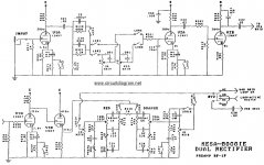
The voltage supply on this project is a SMPS high voltage, variable to over 400vdc. And the same voltage is going to each gain stage. But looking at the different preamp schematics they all have different voltages going to each gain stage. If you look at the attached Mesa Boogie amp, the first gain stage is powered from point E from the power supply which is 402v. And at stages four and five it powered from point C which is 422v.
So my question is, should I change the voltage at each stage to match like the real amps? Or will running all the stages at the same voltage make not that much difference?
They all work and sound great, but will they sound even better at the correct voltages?
Thanks
Rob
So I have built some guitar preamps into a pedal size box. This is using a 120vac converted to 12vdc wall transformer to power these up. I am using a project that has already been verified to work over at DIYSTOMPBOXES.ORG (GTFO - Full tube high-gain pedal (2x 12AX7)). I found someone that is selling PCB boards for this project, and I have changed it over to other preamp designs by using turret terminal boards. I have created four different preamp pedals of famous amps: 5150, Soldano Hot Rod 50, Orange Rockerverb, and Landry LS100. All of these work, and they all sound different. I cannot say if they sound like the real thing, since I never played any of them. I am running these into the return of my Marshall DSL40C. Which has (2) EL34 power tubes.
The voltage supply on this project is a SMPS high voltage, variable to over 400vdc. And the same voltage is going to each gain stage. But looking at the different preamp schematics they all have different voltages going to each gain stage. If you look at the attached Mesa Boogie amp, the first gain stage is powered from point E from the power supply which is 402v. And at stages four and five it powered from point C which is 422v.
So my question is, should I change the voltage at each stage to match like the real amps? Or will running all the stages at the same voltage make not that much difference?
They all work and sound great, but will they sound even better at the correct voltages?
Thanks
Rob
Attachments
As long as all the stages are biased where you want them, there won't be much change in sound with slight changes in supply voltage.They all work and sound great, but will they sound even better at the correct voltages?
The usual reason for feeding the tubes from different voltages is something else entirely: if you feed several triodes from the same power supply, there is a chance of unwanted positive feedback through the shared power supply. This can cause "motorboating" low frequency oscillations, or squeals or whistles, or even high-frequency oscillation at frequencies too high for us humans to hear (radio frequencies, even.)
To avoid this, the power supply is designed to use multiple series resistors, each with its own filter cap, each tap feeding only one or two triodes.
-Gnobuddy
Thanks for the replies!!
I do not know what they need to be biased at. I am just making these per the schematics for the resistor and cap values. The only thing that I do not have a reference from the schematics is the voltage at the plate resistor. I do have this voltage on some of the builds, but not all of them. I am working on my 5150 build, which I can not turn above 9 or 10 o'clock without it squealing. Is the squealing maybe because the voltage is from the same supply? Would filter caps maybe help?
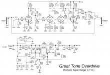
I have attached a copy of the schematic for the GTO project. This is the base project I am using to create these pedals, and adding or changing components to the preamp I am doing. This GTO schematic will show you the power supply I am using. I hope this helps you see what I am doing, and maybe my questions.
I do not know what they need to be biased at. I am just making these per the schematics for the resistor and cap values. The only thing that I do not have a reference from the schematics is the voltage at the plate resistor. I do have this voltage on some of the builds, but not all of them. I am working on my 5150 build, which I can not turn above 9 or 10 o'clock without it squealing. Is the squealing maybe because the voltage is from the same supply? Would filter caps maybe help?
I have attached a copy of the schematic for the GTO project. This is the base project I am using to create these pedals, and adding or changing components to the preamp I am doing. This GTO schematic will show you the power supply I am using. I hope this helps you see what I am doing, and maybe my questions.
Attachments
Guitar electronics is subjective. If it sounds right, it's right...for you!I do not know what they need to be biased at. I am just making these per the schematics for the resistor and cap values.
Thanks for including the schematic. That makes it much easier to understand what you're dealing with....5150 build...squealing...maybe because the voltage is from the same supply? Would filter caps maybe help?
")
Having four gain stages all fed from the same power supply node is not a great idea, and it certainly isn't helping your amp to be squeal-free.
But there are no guarantees that the power supply is the (only) cause of the squealing. You have a lot of gain stuffed into, I'm guessing, a fairly small space (since you mentioned it's in a pedal.) If even a tiny fraction of the output signal leaks back to the input, you'll get squeals and oscillations. This can happen literally through the air (stray capacitance), or due to a slightly imperfect grounding or wiring scheme.
However, fixing the power supply is pretty easy, so I certainly encourage you to start by doing that. I won't hurt anything, and might help with the squealing problem.
I suggest starting by inserting a resistor in the B+ rail, so that V2 is fed from the right side of the resistor, and V1 the left side (in your schematic.) You'll also need a filter cap from the left end of the resistor to ground.
The attached image shows (in red) the changes I'm suggesting. I'm guessing at values that should work; I estimate the 10k resistor will drop less than 20 volts, as there is so little current drawn by V1.
However - the original designer(s) of the 5150 will have dealt with the same problem. What sort of power supply decoupling resistors and capacitors (values and locations) were used in the original? Why not simply copy that, as you are copying the rest of the circuit?
-Gnobuddy
Attachments
Sneak-back though the power supply is typically LOW frequency, motorboating. ThinK: the caps are low-low-impedance at high frequency but high impedance (more sneakage) at low frequency.
"Squeal" is most often THROUGH THE AIR. Stray capacitance. As said: "a lot of gain stuffed into, I'm guessing, a fairly small space". Unfortunate layout, in and out too close. Highs sneak more, but g-amps have treble rolloff, so squeal happens at medium-high frequency.
"Squeal" is most often THROUGH THE AIR. Stray capacitance. As said: "a lot of gain stuffed into, I'm guessing, a fairly small space". Unfortunate layout, in and out too close. Highs sneak more, but g-amps have treble rolloff, so squeal happens at medium-high frequency.
I now know I was over thinking. I attached the schematic I was working off of, that shows the power connections. I did a board with all the points B+, B++, and B+++. Then I realized only B++. and B+++ are needed. Turned the power pot to around 402 vdc, inserted the 10K resistor between B++, and B+++ and sounds pretty good. More stable sounding then without the 10K resistor. Curious about the 4.7 ohm resistor in the ground side? I did not install the (2) 22uf caps. Not sure if they will help?
I do not remember were I got the 402 vdc rating for B++.
On a side note, when comparing the bass on the 5150 pedal, and the Soldano pedal (which are almost the same circuit), the Soldano has a lot more bass. I am wondering if that 47k resistor off of the mid control has anything to do with lesser bass?
Thanks
Rob
- Status
- This old topic is closed. If you want to reopen this topic, contact a moderator using the "Report Post" button.
- Home
- Live Sound
- Instruments and Amps
- Guitar preamp in pedal form