Hi everybody!
I am trying to figure out a way to add an Fx Loop to my CODE 25 amp.
After bouncing back and forward on several forums I figured out that there were 2 3 people before me attempting this. The results obtained vary quite a lot.
Let me describe describe at which stage in the process I am at:
1. Managed to figure out that one of the boards on the CODE is responsible for all the sound processing while the other one is mainly responsible for the amplification.
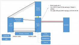
2. The sound is being transferred through the marked 4 conductor cable from the processor to the amp board.
3. This sound is comprised of the guitar sound + effects and the USB sound
4. The bluetooth sound is sent separately through the 3 conductor cable (2 white, 1 black)
5. The Windows USB driver might be buggy
Looking at pictures of CODE 100 and 100H (which both have Fx Loops) I noticed that the sound processing board is identical. It is indeed connected to the amp board through this 4 conductor cable but the conductors are coded as pairs (2 pairs of black white conductors, with black marking pin 1)
So I ended up measuring what is going on on this cable (with the amp powere off):
- Pins 2 and 4 are shorted with eachother both on the DSP board and on the AMP board (0 ohm)
Unplugged the 4 conductor cable and:
A. checked if there is any bluetooth sound coming through. It came allright --> bluetooth sound carried through the 3 conductor cable (albeit channels reversed)
B. USB sound does not come through. Sound card was discovere by Windows (has power)
C. Guitar + effects can be recorded in Windows through USB
D. Neither the guitar sound nor the USB sound come through the speaker / headphones.
E. Line in works ok (channels L and R map correctly), headphones work ok, footswitch works ok
As I became certain that analogue sound is being transferred through this 4 conductor cable, I started experimenting with plugging in only some of the pins, hoping that one pair sends guitar sound and the other one USB sound.
I think it would be the best place to add an Fx loop but the testing left me really confused about what is going on there:
(pins 2 and 4 shorted together on DSP side and on AMP side, measured 0 ohms)
PINS 1 + 2 -> Guitar to Speaker OK; Guitar to Headphones L Only
PINS 3 + 4 -> Guitar to Speaker OK; Guitar to Headphones R Only
PINS 1 + 3 -> Guitar to Speaker OK; Guitar to Headphones L and R OK
In all these configuration the USB sound came through as well, but as mentioned before, I think the USB driver is a bit buggy, I can hear only the left channel.
I really don't understand why pins 1 + 3 are giving sound on both channels, and if these pins would be the right place to add the Fx Loop in.
My gut feeling tells me that actually from the DSP board the sound travels in stereo to the AMP board but I also don't find the logic to that.
I would really appreciate some opinions on that
I am trying to figure out a way to add an Fx Loop to my CODE 25 amp.
After bouncing back and forward on several forums I figured out that there were 2 3 people before me attempting this. The results obtained vary quite a lot.
Let me describe describe at which stage in the process I am at:
1. Managed to figure out that one of the boards on the CODE is responsible for all the sound processing while the other one is mainly responsible for the amplification.
2. The sound is being transferred through the marked 4 conductor cable from the processor to the amp board.
3. This sound is comprised of the guitar sound + effects and the USB sound
4. The bluetooth sound is sent separately through the 3 conductor cable (2 white, 1 black)
5. The Windows USB driver might be buggy
Looking at pictures of CODE 100 and 100H (which both have Fx Loops) I noticed that the sound processing board is identical. It is indeed connected to the amp board through this 4 conductor cable but the conductors are coded as pairs (2 pairs of black white conductors, with black marking pin 1)
So I ended up measuring what is going on on this cable (with the amp powere off):
- Pins 2 and 4 are shorted with eachother both on the DSP board and on the AMP board (0 ohm)
Unplugged the 4 conductor cable and:
A. checked if there is any bluetooth sound coming through. It came allright --> bluetooth sound carried through the 3 conductor cable (albeit channels reversed)
B. USB sound does not come through. Sound card was discovere by Windows (has power)
C. Guitar + effects can be recorded in Windows through USB
D. Neither the guitar sound nor the USB sound come through the speaker / headphones.
E. Line in works ok (channels L and R map correctly), headphones work ok, footswitch works ok
As I became certain that analogue sound is being transferred through this 4 conductor cable, I started experimenting with plugging in only some of the pins, hoping that one pair sends guitar sound and the other one USB sound.
I think it would be the best place to add an Fx loop but the testing left me really confused about what is going on there:
(pins 2 and 4 shorted together on DSP side and on AMP side, measured 0 ohms)
PINS 1 + 2 -> Guitar to Speaker OK; Guitar to Headphones L Only
PINS 3 + 4 -> Guitar to Speaker OK; Guitar to Headphones R Only
PINS 1 + 3 -> Guitar to Speaker OK; Guitar to Headphones L and R OK
In all these configuration the USB sound came through as well, but as mentioned before, I think the USB driver is a bit buggy, I can hear only the left channel.
I really don't understand why pins 1 + 3 are giving sound on both channels, and if these pins would be the right place to add the Fx Loop in.
My gut feeling tells me that actually from the DSP board the sound travels in stereo to the AMP board but I also don't find the logic to that.
I would really appreciate some opinions on that
Attachments
1 picture is worth 1000 words.
Post the schematic and we´re talking.
Until then ....
Specially since
Post the schematic and we´re talking.
Until then ....
Specially since
, imagine us NOT being there.the testing left me really confused about what is going on there:
Hi,
Thank you for the reply. Unfortunately there is no available schematics (to my knowledge) of the Marshall CODE series amps.
Everybody that tried to make this FX Loop ended up experimenting like I did, and with the same results as presented.
I am unfortunately stuck at making guesses and measuring different things to confirm these guesses...
It sounds to me like pin 1 is L audio, pin 2 is L ground, pin 3 is R audio, pin 4 is R ground.
Both channels works when just pins 1 & 3 are connected because the 2 PCBs are probably grounded via a separate connection as well.
The connection is stereo because probably some of the DSP effects are stereo such as flanger, etc.
The speaker works for either connection because there is probably a summing stage on the amp board to sum L & R for the single speaker.
Hi @leadbelly ,
I had the same feeling but I did not want to say it outloud...
Do you have any idea on how to test this? I don't have an oscilloscope, but I do have a multimeter.
If that is the case, as I want just to add a looper pedal (which is stereo in stereo out) to the amp, everything looks smooth. L R FX loop send and return and it's sorted
Regards,
Matei
What kind of proof will satisfy you? A DMM on AC can tell you there is likely an audio signal, but so what, you can already tell that from your testing.
You can probably just temporarily rig up your pedal. It's meant to accept to accept a high impedance guitar input, so it will not burn out anything on the DSP board by drawing too much current.
You can probably just temporarily rig up your pedal. It's meant to accept to accept a high impedance guitar input, so it will not burn out anything on the DSP board by drawing too much current.
Last edited:
Get a scope.
No excuse for not having one nowadays that "hamburger price" small DSOs are available.
No need for great performance, you only need to "see" and follow an Audio signal, easy peasy.
Fully Assembled DSO138 2.4" TFT Digital Oscilloscope (1Msps) + Probe B1 Welded | eBay
No excuse for not having one nowadays that "hamburger price" small DSOs are available.
No need for great performance, you only need to "see" and follow an Audio signal, easy peasy.
Fully Assembled DSO138 2.4" TFT Digital Oscilloscope (1Msps) + Probe B1 Welded | eBay
- Status
- This old topic is closed. If you want to reopen this topic, contact a moderator using the "Report Post" button.
- Home
- Live Sound
- Instruments and Amps
- Marshall CODE 25 Fx Loop