I'm trying to repair a power amp board from a Trace Elliot GP12 SMX AH250 bass head. The power MOSFETs are J50 and K135s. Both the K135s have failed. I'm planning to replace them with Exicon ECF10N20s as these seem to be the only readily available replacement.
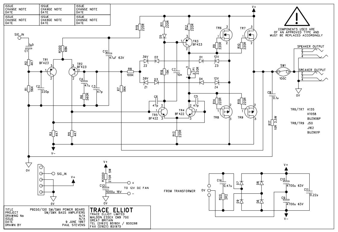
My first question is to check that I should replace all the MOSFETs (i.e. with 2 x ECF10N20 and 2 x ECF10P20) as they need to be matched and can't get away with just replacing the K135s.
My next question is that I understand I would need to bias the MOSFETs once I have done the replacement, via the 220ohm trimpot. However, I have no idea how to do this as I have no experience with power amps. I understand one method is to adjust just enough to remove crossover distortion, which I can understand and can see how to do. The other method relates to setting drain current, but I'm not sure how I would physically go about doing this given the design of the PCB, as there are no resistors in the path between the rails and the drain - do I have to break a track? I'm also not sure which transistors I should measure - TR6, TR7, TR8 or TR9 or what sort of value I would need to aim for.
Any help would be gratefully received.
Yup. You have a "production optimised" circuit. With no easy way to measure the bias current (amongst other sins).
The only option you have is to start at 220 ohm and reduce only as far as to make it sound "not too ugly".
The other problem you may have (and I'm not going to do your homework for you) is that changing output transistors will likely affect the stability of the amp. If they have more gain or are faster you're going to have to tweak the circuit a bit
Thanks for the clarification on setting the bias, that helps a lot.
I'm a bit perturbed by your final comment about stability. Can you explain what you mean? As I said I'm not experienced with this - if I knew the answers or even where to find all the answers I wouldn't need to be asking here
I'm a bit perturbed by your final comment about stability. Can you explain what you mean? As I said I'm not experienced with this - if I knew the answers or even where to find all the answers I wouldn't need to be asking here
Bipolars vary *A LOT* and going from "old" to "modern" in general, speed has gone steadily up, so it´s common that modern replacements are much faster than older ones and so stability problems arise.
That said, both original VFets and Exicon versions are basically same product , so much so that they sell unmounted chips which are then packaged and sold as modern production 2SJ*** , 2SK***, BUZ*** and so on, go figure, all having basically same guts ... which are also sold ready to use as EXCN*** brand.
They are cooking fresh product but following the old recipe, to fill a very narrow and well defined niche in the Audio market.
My point being that the modern ones are equivalent and safe compared to the old ones.
I would use the Exicon products in that 80´s Trace Elliot amplifier and not worry about it.
As of biasing, I would never ever bias them by ear, I´d both use a scope to see crossover waveform disappear and check current through power Mosfets and not letting it go beyond 50mA per device, tops, and much happier with around 30mA
This is not a Hi Fi amplifier where we´d strive to get, say, 0.05% distortion or less, but a Bass amplifier, where somewhat rough sound disturbs nobody, so you can stay on the safe side of the road.
Follow tracks and wiring, and find a point where you can open the path to open the connection to insert your current meter leads in series.
Absolutely worst case, cut a track with a hobby knife, scratch solder mask on both sides so meter probes make contact, and afterwards rejoin separated track sides with a drop of solder.
The original PCB may already have a similar arrangement used at Factory.
In principle, set bias to 0 so you *do* have crossover distortion, drive the amplifier to 1 or 2W RMS into rated load , scope it, you should *see* crossover distortion, and slowly rise bias until it just disappears.
Then for safety, stop driving it and measure current consumption, by opening , say, the +V rail coming from power supply and calculate idle transistor dissipation.
Suppose you have 100mA total, +70V rail and 4 transistors as shown so 2 per rail.
So now you see each one is dissipating (70V*0.1A)/2=3.5W .
That´s a reasonable value, heatsinks won´t feel even "warm" but simply not "stone cold" ... that´s safe, try not to go higher.
IF heatsinks feel warm or hotter, maybe you biased them too high.
Don´t think you´ll reach that, but let´s play it safe, those transistors are expensive.
Almost forgot: measure current consumption when zero biased, and substract that from your calculations, the board itself (the other components) may be using 10 or 20mA for its own needs, those are not going through the power transistors.
You are right, the schematic has some drawing errors.There is no connection on the circuit diagram from the sources of TR6 and TR8 to the output.
1) it´s missing the line connecting Tr6-TR8 sources to speaker out as you noticed.
2) it´s also missing the connecting dots from D1 to TR3 and D4 to TR4
It is a guitar amplifier and the setting doesn't matter much.
Mostly leave the pre set around the centre position.
If the current is too high, the Mos Fets warm up and the gain goes down. Self regulation. Just like a valve does.
They came up with one design that worked and added or removed components as required. Depending on the power required for each model.
If you want, you could use a clamp meter on the mains supply or if you can get to it, the AC supply line to the bridge rectifier.
Last edited:
- Status
- This old topic is closed. If you want to reopen this topic, contact a moderator using the "Report Post" button.
- Home
- Live Sound
- Instruments and Amps
- Setting bias on bass power amp