I play a violin with a piezo pickup that likes to see 5M ohm impedance. I use a 10M ohm input DI box and don't personally find a problem with it being 4 metres down a low-cap cable. I want to avoid a fet buffer on the instrument.
Problem comes when I want to use effects. The Boss OC2 octaver is the first in the chain and has an input impedance of 1M ohm. I know many guitarists use Boss pedals as buffers before other pedals as they have a FET input whether bypassed or on.
Can I simply change the 1M ohm resistor R3 for a 5M ohm to give me a 5M ohm input impedance? or is that likely to screw with something else?
The output from my pickup is also too hot for the OC2 so I will also change the value of R1 or put a trim pot in series.
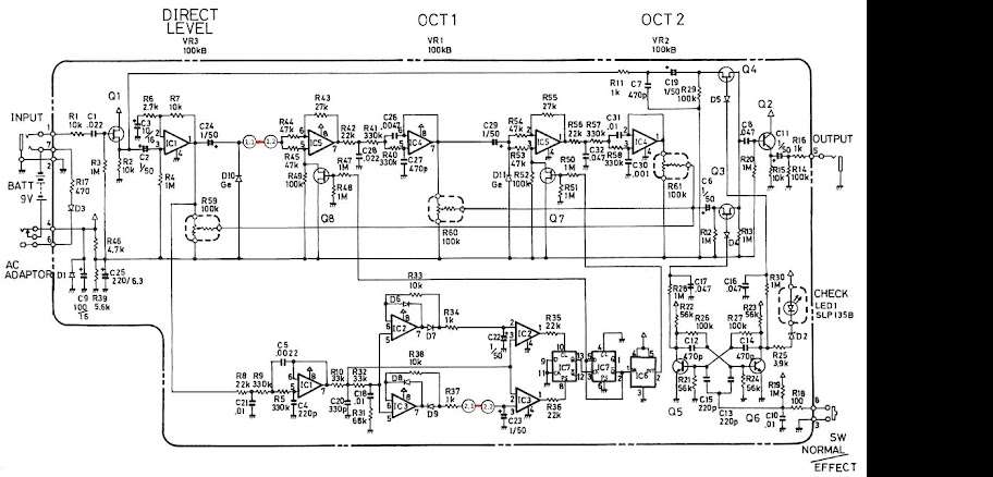
I think this should work.
ok, not completely...
putting a trimmer in series with a 5M input inpedance will not change much, unless use a 10M trimmer. I doubt the results will be fine with this values.
If you really need input attenuation, maybe leave the 1M resistor and change R1 to maybe 1M, this will give you an attenuation of roughly 2:1 and increase Zin to about 2M.
Cheers for that GeorgK.
If I change R1 and R3 to 2.4M each I'll achieve attenuation of 2:1 with a Zin of 4.8M. Is there a downside to this?
If I change R1 and R3 to 2.4M each I'll achieve attenuation of 2:1 with a Zin of 4.8M. Is there a downside to this?
If you really need input attenuation, maybe leave the 1M resistor and change R1 to maybe 1M, this will give you an attenuation of roughly 2:1 and increase Zin to about 2M.
Well, I am somewhat sceptical about dealing with such h enourmous inpedances AND longer cable runs, but it should work out that way.
Some things that came to my mind:
unless you are sure that distortion is already occurring in the buffer stage, you could do attenuation afterwards.
And I am not sure that you won't sacrifice the advantage of yout Hi-Z input with a the considerable length of unbuffered cable. But this is just an idea.
You could also add a JFET opamp buffer, this would give you some freedom in choosing input impedance and adding attenuation if necessary.
Yeah, I know... I did listen to all the usual advice but then I did some listening tests.
I have a Headway EDB1 with switchable Zin and 3.5m of the lowest capacitance cable available (sommer spirit LLX). I have recorded playing slow scales over the instruments full range.
At 1Mohm Zin there is noticeable LF roll off compared to 5M.
20Mohm Zin makes no discernible difference to 5M with my ears.
Swapping the sommer cable with a 6m fairly standard guitar cable of unknown capacitance I can hear the HF is attenuated. The 3.5m sommer cable sounds totally fine to me with 5Mohm Zin, infact if anything I'd like to remove a bit more HF.
Basically I'm fairly sure I want 5M Zin and to lose some signal voltage (of unknown amount due to having no scope!) Sure enough to try it if I know the method will achieve those specifics and not blow my fave pedal up!
I'm also 95% sure I don't want a buffer on the instrument as it's only small and pretty hard to work out where the battery would go. It's really not so easy as a guitar. When I am using effects I am always using the OC2 first in line so it make more sense to me than having another box.
Anyway, that life story is my thinking!
So... making those changes will achieve that aim? I'll give it a go and listen, if it works, great, if it doesn't I'll have to think where I want to compromise.
Cheers
You can add capacitance to reduce the output level and HF extension, if you need a bit more HF extension/higher bass cutoff you can then reduce the resistor value.
...The output from my pickup is also too hot for the OC2...
Put a few thousand pFd across your piezo pickup. This will NOT cut highs, as it would for a resistive or inductive source. It will reduce output equally at all frequencies. It will be less sensitive to resistive loading; you may have fine bass with 1Meg loading.
Or you could remove R6 in your OC, eliminate that early gain which an older magnetic pickup may need but your piezo does not.
Making gain of IC1 adjustable would be a perfect way for an attenuation after the buffer.Or you could remove R6 in your OC, eliminate that early gain which an older magnetic pickup may need but your piezo does not.
I would prefer this over a large resistor on the input.
I rather think the OC stays clean when bypassed?
So a capacitor across the pickups reduces output impedance and signal voltage which is the same effect as changing the values of the potential divider at the OC2 input.
So does the use of a capacitor there have an advantage over the potential divider? Do they have pro's and cons or just 2 different ways to "skin the cat" (as they say)
So does the use of a capacitor there have an advantage over the potential divider? Do they have pro's and cons or just 2 different ways to "skin the cat" (as they say)
I never tried a parallel cap, and I admit that I have no idea if this could work in a satisfying way...
But if it does, I would prefer it over the resistor solution.
if not, I personally still would try to put a miniature buffer on the violin side.
But if you do not want this, another way to go could be to put a 10k trimmer in place of the FETs source resistor, wired just like a volume pot. This would allow you to adjust both the bypassed and processed signal level of the OC without adding MOhms of serial resistance to the input. Works only with the FET itself not being already overdriven by the PU of course, but leaves you with a lot of freedom as far as the value of the input parallel resistor is concerned.
Thanks all definitely enough ideas to start experimenting now and see what works, just left with one question though...
GeorgK - what is the problem with using large resistors in series on the input, you seem so against it I guess I'm missing something obvious?
GeorgK - what is the problem with using large resistors in series on the input, you seem so against it I guess I'm missing something obvious?
It's more a feeling that you should avoid some things that maybe could be solved differently...
The signal after the 5M serial is very sensitive against interference (As if a plain piezo would not be enough... 🙂 ). Ok, not a real problem as long as the resistor is close to the FET.
Then the large resistor is a potential noise source.
And the FET has a certain input capacitance that might affect your tone as there is such large additional source resistance.
I feel that, if you can drive the FET with as much level as possible (as long as it is not overdriven of course), you have one potential noise source less.
Or call it that would find the solution with post-attenuation more elegant as the Fet then is as close to a real buffer as possible when being fed with a highly "pure" signal.
Just my 2 cents.
Your 2 cents are appreciated and sound sound 😉
I just went round a friends workshop to measure output voltage and capacitance of my PUP.
Wasn't convinced of the capacitance measurement accuracy but it was coming out at 420pf
The voltage, measured on 'scope, was 3v peak with hard playing and, if I really tried I could get transients upto 5v! (though I'd never play like that in real world).
Interestingly there was a substantial DC offset though, the polarity depending on the bow direction. I guess that will disappear with the 1st capacitor it goes through leaving a peak to peak voltage maxing at around 2.5v.
Seems to me I don't really need to be going into anything with that kinda level? In that case the capacitor level reduction make sense as it will also improve input impedance problems and I can probably mount it in the violin output socket without it being intrusive.
If the cap solution delivers the sound you want, definitely go for it.
I wonder if this works.
I suppose you have a bridge pickup? That could explain why it reacts to the direction of pressure, resulting in the DC offset you can see as long as the impedance of the scope is high enough.
3 volts peak level means 6V pp? Agreed, I think you can forget a 9V powered buffer with this. Anyway, if somehow the signal does stay clean when bypassing the OC, you could try tapping the source resistor as I suggested, especially if the result with the cap should not prove satisfying.
Good luck, let me know how the parallel cap works.
I'm a little late, but if the previous suggestions don't work out, then you might consider my 1st choice which would be replacing the FET with a MOSFET a la Jensen schematic AS098:
http://www.jensen-transformers.com/wp-content/uploads/2014/08/as098.pdf
EDIT: oops, just realized PN4393 is a JFET and obsolete. Let me think about it.
http://www.jensen-transformers.com/wp-content/uploads/2014/08/as098.pdf
EDIT: oops, just realized PN4393 is a JFET and obsolete. Let me think about it.
Last edited:
One problem is thermal noise. Big resistors are noisy. As in, lots of "hissssss" in the signal from your violin.what is the problem with using large resistors in series on the input
Another problem is the potential for treble loss due to the high source impedance, combined with the input capacitance of the JFET.
I too was going to suggest using a parallel capacitor to lower signal level and source impedance, but I see that suggestion has already been made a couple of times. It's a good suggestion, and I endorse it. I have used the same approach with piezo pickups on cheap record players a long time ago.
My mom used to have a piezoelectric gas lighter to use with the kitchen stove. When you pulled the trigger, a spring was compressed and then released a small hammer which whacked a piece of piezoelectric ceramic. In response, the piezo element generated enough voltage to make a big fat spark, hot enough to light the gas stove.
My point: piezoceramics can make startlingly high peak voltages in response to heavy transient impacts. The 5V you measured from your violin is a case in point. That is high enough to cause momentary harsh clipping in just about any typical battery powered instrument preamp.
I suspect a good amount of the harshness often attributed to the piezo pickups on electroacoustic guitars is caused by the same thing - large short-term transient voltages that briefly clip the onboard guitar preamp.
-Gnobuddy
One problem is thermal noise. Big resistors are noisy. As in, lots of "hissssss" ....
A large resistor *shunted* by a lower impedance, the resistor hiss voltage divides down.
Using JFETs, go as high as possible on that resistor.
420pFd is not unlikely for a piezo pickup. Taken alone, this is 1Meg reactance at 380Hz, so 10Meg(!) at 38Hz, 100K at 3.8KHz, 50K at 7.6KHz.
So we see that a 1Meg load gives a bass-cut at 380Hz, which is high even for violin. Also that the hiss of a 10Meg resistor is cut about 100:1 in the hiss frequencies, a few KHz.
If the 420pFd pickup is shunted with say 3,800pFd (total 4,200pFd), the output voltage drops from 5V max-peak to 0.5V max peak, a more tolerable level. Impedance becomes 100K reactance at 380Hz, so 1Meg at 38Hz, 10K at 3.8KHz, 5K at 7.6KHz.
A 1Meg load makes a 38Hz bass cut, "full bass" for most non-bass instruments. Hiss of a large load resistor is also 10X lower.
With resistive or inductive sources we do NOT hang capacitors on them because it will reduce treble. But a *capacitive* source into a cap makes a simple voltage divider without frequency discrimination. Reasonable resistive loads will cause less freq disc than the pickup alone.
In short, it becomes a more suitable source for reasonable loads.
A 3,300pFd NP0 or Mica cap is very inexpensive. Worth a try.
FWIW: a 100 foot cable is about this magnitude. That does however invite another 90 feet of power and lighting lines to induce hum/buzz; bunch it up.
There is also the approach of feeding the piezo into what is essentially a dead short - the virtual ground input of an op-amp integrator stage.But a *capacitive* source into a cap makes a simple voltage divider without frequency discrimination. Reasonable resistive loads will cause less freq disc than the pickup alone.
Fed into a virtually zero input impedance, the current from the piezo rises with frequency (+ 6 dB/octave). The integrator compensates with its -6 dB/octave response.
The net result is a flat frequency response, bass response down to the lowest frequency at which the integrator still integrates, and good immunity from hum due to the very low impedance at the input.
This arrangement is sometimes called a "charge amplifier". I've had good results with it in an application where I was using a piezoceramic disc as an accelerometer in a motional-feedback woofer design.
It would be easy to go this route with a DIY preamp, but not so easy to convert the Boss pedal to charge amplifier mode.
-Gnobuddy
There is also the approach of feeding the piezo into what is essentially a dead short - the virtual ground input of an op-amp integrator stage.
This is interesting, I wonder what the downside is as I have never seen this in a PU amp stage yet?
I have always regarded the behavior of a piëzo as roughly a current source in series with an internal capacitance (would you agree?), so the arrangement would make sense.
- Status
- Not open for further replies.
- Home
- Live Sound
- Instruments and Amps
- Modifying input impedance of Boss OC2 to use as piezo buffer