Hi All:
Hello
I'm new to diyAudio. I've been day-dreaming (for years now) about quitting my day job and building guitar amps for a living. I realize that it's a hard way to make a dollar, so I've kept the day job so far. Bought Tubes and Circuits - by Bruce Rosenblit a few months ago, been reading that, learning from other forums, and have been playing with a couple of my own amps. Having fun so far. But...
Cry for help!
One of my amps is experiencing an issue. I'm a little baffled. Hope someone can help.
It's a Vox AC15C1. EL84 Cathode biased. I played it for 6 months without even looking at the tubes. Then I did and noticed one was a little red. I put in another set of used JJ EL84s I had lying around. One red-plated. I put in a new set of matched JJs. One red-plated.
The red-plating follows the tube on all 3 sets. If I swap left and right the same tube red-plates.
I took the non-redplating JJ from each set and installed them both. One red plated.
My amp bias calcs
I researched how to calculate all my voltages, currents, and plate dissipations. I an an electrical engineer, so very comfortable with these calcs. Here are the stats:
V_Plate_Cathode1=323V, V_Plate_Cathode2=321V
I_Plate1=48mA, I_Plate_2=48mA
P_Plate_1=15.4W, P_Plate_2=15.3W
You might get different power numbers if you do a P=V*I. The above voltages were measured with a Fluke 233 and calculated with excel. I rounded the above for simplicity.
I did subtract my screen current, so yes, my plate wattage is actually that high. Screen wattage is an additional 1.7 Watts per side. So the whole tube is running at about 17W!
Tube spec is 12W. I'm running at 128% over, which is high, but I'm not sure if it's really "Vox High". Of course I don't know my actual cathode current split, so one tube is running higher (obviously the red-plating one).
Vox doesn't publish their bias recommendations, but from what I can gather, in the low 320's is a "good" plate-cathode voltage for a Vox AC15C1. The plate current is a bit high I think, but again, no Vox Spec (jerks).
I can't even pay for help...
I'm a natural diy'er. I love fixing myself. Still, I thought I'd try to pay my way out of this issue.
I brought it to one reputable amp tech. He really didn't want to look at a $500 PCB amp.
I emailed the store where it was purchased. They want $75 to look at it, plus parts. And their amp tech told me that "cathode bias amps don't need to be re-biased". I'd like to defer to a more experienced tech, but everything I've read online says that's crap. Especially on an amp that is biased super hot out of the factory and mass manufactured (read: high variability in tolerances). How can I trust an amp tech that tells me my cathode resistor value is fine without even knowing my bias voltage/currents. Bringing it to him sounds like a money pit...
I contacted Vox's Canadian support company. I told them the situation and that I'd like to buy a resistor higher than the 119ohm resistor installed. I asked them if they could sell me any additional cathode resistors in the 130-150 range. They said "Oh the 119 in their should be fine. We think you have an output transformer issue". That makes no sense to me. I think if it was an output transformer issue the issue would follow the socket, not the tube.
I tried searching mouser/digikey for a resistor that would fit the bill - nothing. It's such a tight area that any old wirewound resistor won't fit. I need the Vox part (but in a 130-150ohm instead of the stock 120ohm).
What to do?
Here are the options I see:
- Try to jimmy in a cathode resistor. It will involve buying an odd size and re-locating it somewhere on the chassis. Not something I want to do, but an option.
- Increasing screen resistors. This is just my theory. It's not something I've seen suggested elsewhere. Most people talk about adjusting the cathode resistor.
- Searching for lower rated tubes. My matched pair is a medium warmth JJ. My tube distributor says he can get me some colder tubes. How does this work? I guess some tubes have higher operating-point impedances due to construction differences?
If you got this far, I thank you for reading my first novel of a post on diyaudio. Appreciate any help or guidance that anyone can provide.
It runs hot, class A amps do run hot anyway, though we try to keep it within tube spec. But a guitar amp is like a drag racer on tires, it wears them out.
Please tell me it is a 120 ohm resistor that you measured at 119. I cannot imagien anyone designing a guitar amp that needed a 119 ohm resistor. And if the stock item is 120 ohms, a 10% jump won't change much. More like 150-200 anyway.
Tech won't lower himself to look at a circuit board? Can't be bothered with an amp that was ONLY worth $500? Hard to respect that guy. if you are in a big city and the guy can make a living only working on Vintage Fender amps, more power to him. But when I hear that sort of boast, my first reaction is he learned to do some things to old fender amps and that is all he knows. Good luck finding a modern amp that is hard wired rather than on a board. And as someone who ran a pro audio shop for 30 years, I don't get new customers by treating new ones and ones with inexpensive amps like dirt. I treat a guy and his $300 amp with respect, and he comes to me when he has a $2000 amp. That is just business. Imagine a chef that refuses to cook anything but lobster.
Most shops have a bench fee or bench minimum. In my shop I had a one hour minimum, which was $60. $75 is not out of line. They are working on your amp, it requires not only a fcility, but also experience. You have to pay for that. What do you think they ought to charge? My $60 an hour is not over average. What does your local car service charge for labor? I am certainly as good a technician as they are mechanics. You are an engineer? Tell yourself what you make an hour for your services. I bet you don't or didn't work for $15.
The only way to adjust the bias on a cathode biased amp is to change the resistor. I don't recall ever seeing an adjustable one, though all it would take was a high wattage rheostat. But when the current goes up through it, the voltage drop across it also rises, so it tends to take care of itself. Most small amps like this will take pretty much any tube you stick in there without need to alter anything. That is why the tech said the 120 ohms was OK without even seeing it.
If you want to change it, and I am not saying you shouldn't, why would it be difficult to put a different value part in there? Isn't it a regular 5 watt rectangular cement resistor? Pull it out and put a 5 watt 180 in its place, the size wil be the same. Or nothing wrong with mounting one of those finned aluminum jobs like Dale makes on the chassis and running two wires over to the circuit where the 120 was.
The screen grid does control tube current, try disconnecting one and watch the tube current go to nothing. It is a valid route to controlling current, but so is the cathode. But as you raise the cathode resistance, the tube current drops, but then the B+ supply rebounds by rising. So you wind up chasing your own tail.
A word about bias. The unwashed internet masses worship bias. They think it is some critical super precise thing. They like to install 10-turn potto adjust it, so they can tweak every last 1/100th of a volt. But consider that the average mains voltage hops all over the place all the time, and at 120v mains a 360v B+ will jump 3 volts for evey volt the mains shifts. So much for 1/100th of a volt settings. But while we have these "rules" like 70% of max for AB amps, in reality, we want the tube cool enough it doesn't melt down, but hot enough not to be unlistenably crossover distorted. There is a wide range in there of totally acceptable bias levels. Some amps like the Vox series run really hot, yet gain monsters like the Peavey 5150 run super cold, as in 120w amp that idles power tubes as low as 11ma. So when someone decides their Champ needs to be "rebiased" every time a tube is replaced, they are misguided.
Depending on the year of manufacture, some use 100R 5W cathode resistors, some use 150R 5W. All have 100R 1/2W screen grid feed resistors with 320-350V on the Anodes and screen grids as normal.
Vox do not use JJ valves as they seem to be sub standard. I use Russian 6p14P or 6BQ5 with no issues at all.
If you are concerned about the dissipation, class AB is normal, increase the cathode resistor by 22R. It makes little difference to the sound.
Vox do not use JJ valves as they seem to be sub standard. I use Russian 6p14P or 6BQ5 with no issues at all.
If you are concerned about the dissipation, class AB is normal, increase the cathode resistor by 22R. It makes little difference to the sound.
And.... so-what if a plate glows a little?
The electrodes are run RED-hot for pump-out. Clearly they won't melt run a little red.
While this is a quite-different field, several Transmitter tubes *normally* "show color" when worked at their ratings.
And EL84 is about the cheapest bottle around. No shame in frequent replacements. (This is part of the "price you pay" when running the little VOX compared to a more conservative design.)
But yeah: 180-200 Ohms will cool it down some.
> I don't know my actual cathode current split
I would say this is worth knowing, in any case of apparent unbalance in a common-bias scheme. In hay-wire construction, you could simply insert 1 Ohm resistors in the cathode wires and bridge your meter across them. In PCB; well, there are reasons to avoid PCB.
You can insert 1r resistors in the plate leads (unless it is ALL PCB?) but this is Very Dangerous to measure. Many techs do it similarly (read OT DCRs then read OT voltage drops). I should not be a technician/snob, but I have known Engineers who should not try this without CPR handy.
You can buy BiasRite and similar adaptors which break tube from socket and bring out test points including current.
You can use an IR thermometer to read apparent plate temperatures. This will reveal significant unbalance across a pair. It should be a handy way to quick-check operating bias when an amp has no test-points and the job does not call for installing such, but you don't want to send an amp out "fixed" if the bias is way-out.
Hmmm... BiasRite is a complete kit with dedicated meter, and seems to be octal-only?
Hoffman and others can sell the plug, shell, socket, and maybe resistor and terminals to assemble your own; it must exist pre-assembled somewhere. Though maybe I am only dreaming of a 9-pin bias adaptor.
Hoffman and others can sell the plug, shell, socket, and maybe resistor and terminals to assemble your own; it must exist pre-assembled somewhere. Though maybe I am only dreaming of a 9-pin bias adaptor.
And.... so-what if a plate glows a little?
The electrodes are run RED-hot for pump-out. Clearly they won't melt run a little red.
Pump-out takes a little less time than the hundreds or thousands of hours in normal operation
")
Metals tend to bind gasmolecules.
Heating the electrodes red hot releases most of them, so that is why they do that while pumping the gas out of the bottle.
Running the anode (and/or screen grid) red hot in an amp, may release some more gasmolecules that are now trapped inside the bottle.
This can make a valve less stable and reduce usefull service life.
Incidental (and moderate) redplating doesn't kill a valve, prolonged redplating will.
While this is a quite-different field, several Transmitter tubes *normally* "show color" when worked at their ratings.
Now that is comparing apples to pears as we say in Dutch
We are not talking about different applications, but different technology here:
Some transmitting valves have a zirconium coated anode, where the zirconium is there to trap stray gasmolecules just like the silver flash getter does on other types. The key here is that zirconium only works at very high (red) temperatures.
In short: redplating receiving types shortens their service life, while a transmitting type like the 833 will have reduced life when it is operated without readplating
And EL84 is about the cheapest bottle around. No shame in frequent replacements. (This is part of the "price you pay" when running the little VOX compared to a more conservative design.)
Best way to cool down a hot Vox is to play it full blast

The speakers will take part of the heat.
In the case of the topic starter however, I think the EL84s that you tried are not completely according to spec.
It's not that they can't handle enough power: some seem to be able to take 14-15W without redplating which is actually quite good.
The problem is that apparently they need more resistance in the cathode, indicating lower transconductance.
It's a bit like they are in between an EL84 and a 6V6.
The cathode resistor in the original AC30 is only 47 ohms for four EL84 at around 320V. That compares to less than 100 ohms for a pair, while the JJs go red at 120 ohms. No redplating with Philips/Mullard or even Chinese.
Conclusion: save the JJs for adjustable fixed bias amps and get a different brand for the Vox.
(or replace the resistor with at least 150 ohms)
Measure the grid voltage for both tubes using a high impedance meter. That might be interesting.
What value is the grid-to-gnd resistor for the cathode biased output tubes?
Can you post a schematic?
Might it be oscillating at a high frequency?
Ughh - I subscribed via email to this thread and it was going to junk mail. Hadn't thought anyone had replied.
I will try measuring grid voltage tonight. Grid to ground resistor? Might you mean cathode to ground resistor? If so, that's 120ohm (I measured 119ohm).
I'm starting to suspect a high frequency oscillation.
Schematic is attached. Not the official, but everything I've checked seems accurate. Page 2 shows the output stage.
Attachments
The AC15C1 is designed to run very hot, the most common mod is to lower the screen voltage to take the dissipation down a bit, followed by changing the cathode resistor if you are really concerned about tube wear, but it is a guitar amp after all...
Interesting.. I was wondering if I could change out those screens for a higher value. They're 470ohm now, and standard 1/2 watt resistors, and fairly accessible.
Please tell me it is a 120 ohm resistor that you measured at 119. I cannot imagien anyone designing a guitar amp that needed a 119 ohm resistor. And if the stock item is 120 ohms, a 10% jump won't change much. More like 150-200 anyway.
It is supposed to be 120ohm.
$75 is not out of line. They are working on your amp, it requires not only a fcility, but also experience. You have to pay for that. What do you think they ought to charge? My $60 an hour is not over average. What does your local car service charge for labor? I am certainly as good a technician as they are mechanics. You are an engineer? Tell yourself what you make an hour for your services. I bet you don't or didn't work for $15.
Hey, sorry. I didn't mean to insult you or anyone in the trade. To be honest, you'd probably be surprised how little engineers often make. Oh, everyone knows one or two who makes a lot, sure. I know someone with just high-school who makes triple my salary.
It's a supply and demand thing. There's a lot of us. In Canada right now I saw a news article saying 30% of engineers in Ontario are un-employed (or under-employed). If you think the rest of us are making a lot of money with that kind of hunger for work (competition) then you'd be wrong.
Anyway, my comment about the guys rate had nothing to do with whether he was worth that kinda money. It just had to do with whether it made sense to start paying big money (compared to the cost of the amp... ) on the thing.
You can pick up the amp for $500 used. If he spends a day on it, I could have had another amp. Besides, I want to learn about tube amps - that's the key reason I'm poking at this thing.
If you want to change it, and I am not saying you shouldn't, why would it be difficult to put a different value part in there? Isn't it a regular 5 watt rectangular cement resistor?
Yes. Very difficult - maybe impossible to replace the cathode resistor. I am well accustomed to using digikey, mouser, and newark. Used to design PCBs for a living. I cannot find a replacement resistor that is 5W and that small. And the resistor is constrained in X, Y, and very much Z. And it's radial leads.
The only way to replace it is to install wires on the PCB and relocate the resistor. Which is doable and I'm keeping that option in my back pocket.
A word about bias. The unwashed internet masses worship bias.
I'm not doing any bias worshiping. I have a tube that's glowing red hot and and everything I've read (from the internet masses granted) is that I shouldn't run my tubes that way - and that the tubes may even be ruined by running them this way for a second.
And.... so-what if a plate glows a little?
The electrodes are run RED-hot for pump-out. Clearly they won't melt run a little red.
While this is a quite-different field, several Transmitter tubes *normally* "show color" when worked at their ratings.
And EL84 is about the cheapest bottle around. No shame in frequent replacements. (This is part of the "price you pay" when running the little VOX compared to a more conservative design.)
But yeah: 180-200 Ohms will cool it down some.
> I don't know my actual cathode current split
I would say this is worth knowing
Sorry for the chain of replies. I felt obliged and thankful for everyone's responses and wanted to get back to the thread as quickly as possible, but was in a rush.
I measured my actual cathode currents. I did so by getting the DC resistance across the coil-to-center tap and then measuring the voltage across the same. My currents are 45.2 and 42.65 mA. Red-plating on the 45.2mA tube.
> 45.2 and 42.65 mA. Red-plating on the 45.2mA tube.
Assuming near-same plate-cathode voltages, that's only a 6% difference. One may be "redder" than the other, but you don't expect red/not-red for a 6% difference.
Also when you take 312V p-k, and knock-off 10%-20% for EL84 G2 current, it is very close to 12W.
You could change 120r to 150r-200r. Actual dissipation is near 1W; a 2W part may live forever. (Yes, they do make parts rated 5W in the space of an old 1/2W part-- they run HOT at full power.)
If easier, it may be more elegant to fiddle R87 R88 in power supply to just drop the whole B+. This is pulsating current into peak-catcher so obvious V/I figures go astray. I'm getting a guess like 300r-500r at 7-10W, which leads to huge resistors.
Screens can be dropped (as said) at R80. Lower Vg2 has the same effect as more Vg1, but 18 times less effective. Changing R71 to 5K may be a 50V drop, a lot cooler. Maybe too much loss of LOUD power.
Experimentation wanted. If I really cared about this beast, I would run a lot of points out to where I could toss various values on and test quickly.
And it may just be that all your JJ tubes have been on the hot side of tolerances.
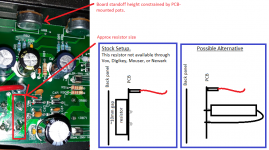
If there is so little space for the cathode resistor, where does it radiate its heat?
On the other hand, it is dissipating less than 1,5W. A 3W resistor might fit?
You can also reduce the current through the EL84s by increasing R80 to lower the screen voltage.
Had a big response typed up and the web site timed out.
I drew a picture to show you the cathode resistor situation. It is possible to relocate the resistor on the other side of the PCB. Won't be pretty, but will work.
> Assuming near-same plate-cathode voltages, that's only a 6% difference. One may be "redder" than the other, but you don't expect red/not-red for a 6% difference.
Also when you take 312V p-k, and knock-off 10%-20% for EL84 G2 current, it is very close to 12W.
I did measure G2 current (by measuring screen resistance/voltage) and already subtracted that off.
I did another test last night and cathode watts are about 14.5, screen watts 1.5. So overall watts ~16W. So you're right - about 10% less, but I had already taken that value off.
If easier, it may be more elegant to fiddle R87 R88 in power supply to just drop the whole B+. This is pulsating current into peak-catcher so obvious V/I figures go astray. I'm getting a guess like 300r-500r at 7-10W, which leads to huge resistors.
Interesting idea. I will definitely keep that as an option.
Not sure how R71 would work - looks to be a part of reverb circuit to me.Screens can be dropped (as said) at R80. Lower Vg2 has the same effect as more Vg1, but 18 times less effective. Changing R71 to 5K may be a 50V drop, a lot cooler. Maybe too much loss of LOUD power.
Experimentation wanted. If I really cared about this beast, I would run a lot of points out to where I could toss various values on and test quickly.
Well, that's the thing. I'm not in love with it. But I'm having fun with the project of trying to fix it. Still, I did think about selling it. But I don't want to sell it in a dangerous state and not tell the buyer - that'd be a bit dishonest. But I also don't want to sell the amp as "broken" either.
Attachments
- Status
- This old topic is closed. If you want to reopen this topic, contact a moderator using the "Report Post" button.
- Home
- Live Sound
- Instruments and Amps
- Red-Plating Amp