Hi guys,
I've been browsing these boards for a while, and I'm hoping some of the knowledgeable people on here can help with an issue I have with a home built amp.
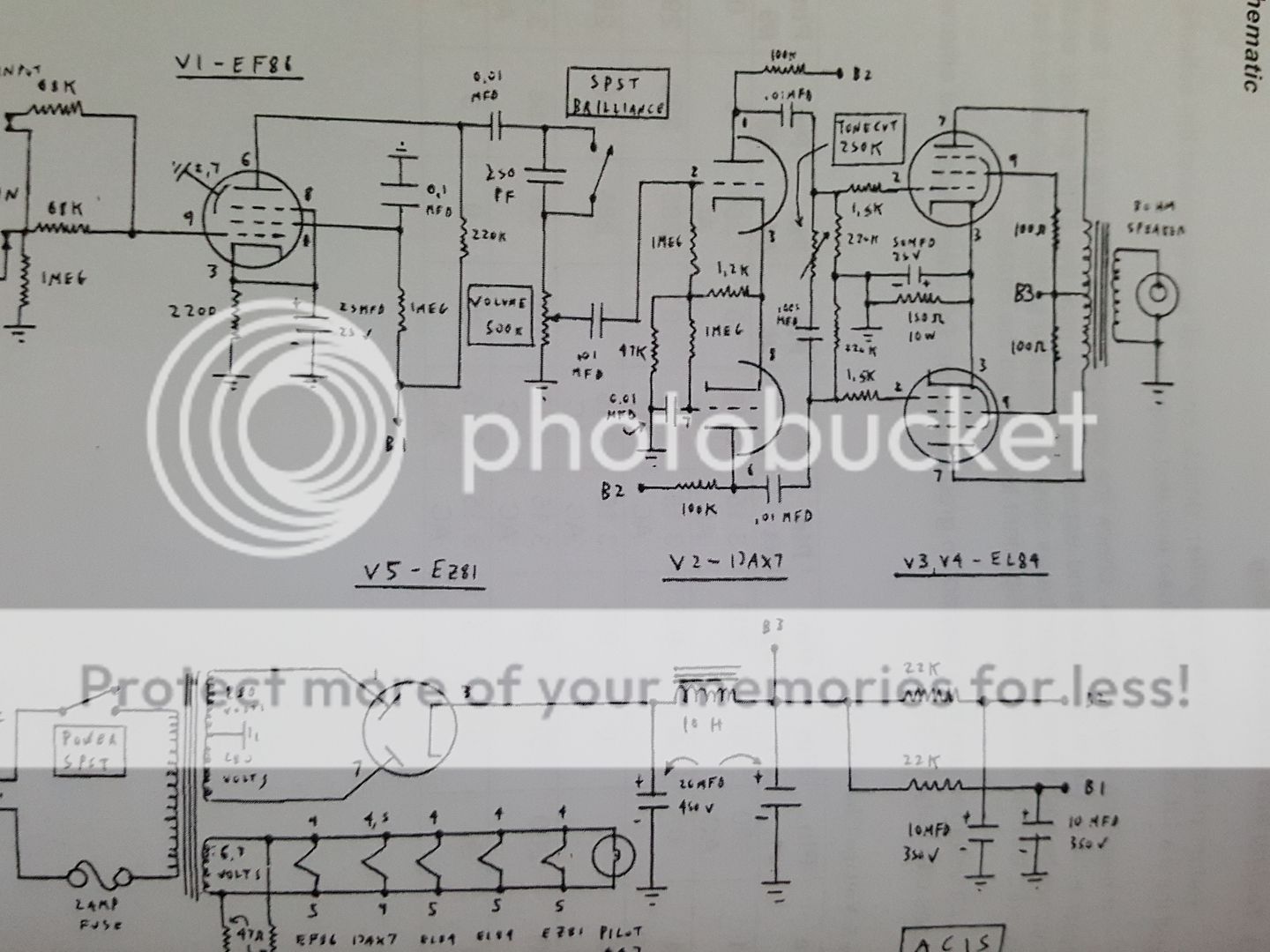
It was loosely based on an AC15, but with 6V6GTs instead of EL84s. I have got the power tubes biased correctly, and slightly changed the preamp section (EF86). However, I have some hum/buzz occurring when I turn the amp on. When I turn the volume up it appears more, and has a sort of modulation effect. Also, when I touch the chassis, the hum/buzz gets quieter.
I'm thinking there is a ground loop somewhere, however, I don't know where to start.
I've been browsing these boards for a while, and I'm hoping some of the knowledgeable people on here can help with an issue I have with a home built amp.
It was loosely based on an AC15, but with 6V6GTs instead of EL84s. I have got the power tubes biased correctly, and slightly changed the preamp section (EF86). However, I have some hum/buzz occurring when I turn the amp on. When I turn the volume up it appears more, and has a sort of modulation effect. Also, when I touch the chassis, the hum/buzz gets quieter.
I'm thinking there is a ground loop somewhere, however, I don't know where to start.
Here is a link to the schematic:
Link
I have swapped the 100R resistors on the power tubes for 470R (1W) and placed a 300R (5W) resistor on the cathode.
For the preamp section I had this in mind:
Link
However, before I got carried away I thought I'd best just test it with the EF86 in the circuit. On that preamp schematic the 47k and 1M resistor are draw the wrong way around.
So I have basically the input straight into the grid of the EF86 then the normal AC15 circuit for now.
I have my CT grounds, Filter caps and cathode resistor at one ground point, and all the other grounds near the input.
I should also note I'm using 6N2P-EV tubes, which are identical to ecc83/12ax7 except pin 9 is an internal shield which is grounded (by the input jack).
Link
I have swapped the 100R resistors on the power tubes for 470R (1W) and placed a 300R (5W) resistor on the cathode.
For the preamp section I had this in mind:
Link
However, before I got carried away I thought I'd best just test it with the EF86 in the circuit. On that preamp schematic the 47k and 1M resistor are draw the wrong way around.
So I have basically the input straight into the grid of the EF86 then the normal AC15 circuit for now.
I have my CT grounds, Filter caps and cathode resistor at one ground point, and all the other grounds near the input.
I should also note I'm using 6N2P-EV tubes, which are identical to ecc83/12ax7 except pin 9 is an internal shield which is grounded (by the input jack).

the PB link wasn't loading, so I copied the image directly.
with the volume down you also have noise?
If you remove the PI tube is there any noise? or try grounding the 6v6 input.
Check from the back to the front of the amp starting with the power tubes to find were the noise is introduced.
As you said, increasing the volume increases the buzz means that there is something before the volume control, but it could be something in a later stage messing with the input.
A bad connection could also produce some noise. Have you checked for bad solder spots or dirt in the tube sockets?
I managed to have a quick look after I posted last (two kids under 2, is killing my spare time!) And When I short out the input jack, everything goes silent, even with the volume all the way up.
I also noticed that with the volume up, if I wave my hand around the input jack area, it changes the intensity (if that makes sense) of the noise.
I also noticed that with the volume up, if I wave my hand around the input jack area, it changes the intensity (if that makes sense) of the noise.
I have just been through the loop with hum on a valve/tube mixer.
1/ Valves should be kept away from mains transformers.
2/ Grid stoppers should be right at the valve grid.
3/ Heater wires should be kept away form audio signals.
4/ High voltage AC lines should be kept away from audio.
5/ If using a pcb use copper pours connected to ground.
6/ Keep wires short as possible especially on input circuit.
7/ Earth the zero volt line once.
If you have a switched jack, you can wire it so that the input is grounded (shorted to ground) when nothing is plugged in.When I short out the input jack, everything goes silent, even with the volume all the way up.
This is a good idea, because when nothing is plugged in, it prevents the input from acting like an antenna, picking up all sorts of interference.
I also recommend using shielded cable from the input jack to the grid stopper of the input valve, for the same reasons.
Is this with a guitar plugged in? If not, it might be nothing more than the input wiring picking up stray interference and hum from the electric (AC) potential of your body. Wiring up the input to a switching jack as described above (shorting to ground when no guitar is plugged in) should solve this problem.I also noticed that with the volume up, if I wave my hand around the input jack area, it changes the intensity (if that makes sense) of the noise.
If this is happening even with a guitar plugged in, you're probably dealing with an amplifier that is oscillating - most likely at a frequency much too high to hear. The goal in that case is to stop the oscillations, which, unfortunately, is potentially a more complex task, as there are several possible causes.
I notice there are no grid stoppers on V2 - adding them might be a place to start.
-Gnobuddy
Right, I have managed to sort out the annoying hum/buzz noise. I checked all my heater wiring and re-terminated the cathode resistor and bypass cap.
Now, I have another issue. When I crank the amp up fully (I use a THD hotplate) I get a really horrible fuzz sound and almost like a farting noise when strumming the bass strings hard, would increasing the screen resistors on the power tubes help alleviate this problem, or could it be within the design of the amp?
Now, I have another issue. When I crank the amp up fully (I use a THD hotplate) I get a really horrible fuzz sound and almost like a farting noise when strumming the bass strings hard, would increasing the screen resistors on the power tubes help alleviate this problem, or could it be within the design of the amp?
There are at least two possible causes for what you're hearing: either severe blocking distortion, or high-frequency oscillation manifesting itself in ugly ways.When I crank the amp up fully (I use a THD hotplate) I get a really horrible fuzz sound and almost like a farting noise when strumming the bass strings hard
My hunch is that you are dealing with the first of these two problems - and that the blocking is happening in the EF86 input stage. (This is based on my own recent struggles with a pentode preamp stage of my own design.)
You may know that this "classic" pentode input was actually taken straight from the valve databooks, and it was never designed for guitar - it was designed to use with microphones, tape recorder playback heads, and other low-level audio signals. It was also designed for Hi-Fi (or at least, medium-Fi), which includes bass response down to well below 20 Hz. In many ways, it is not really well suited for guitar use, which is probably why Vox and others quickly abandoned it.
Still, you can certainly improve it. My first suggestion is to reduce the value of the EF86' cathode bypass capacitor. I calculated that 5 uF of capacitance here, is enough to fully bypass even the lowest guitar note (83 Hz, open low E string in standard tuning.)
Using anything more than 5 uF here won't benefit you in any way, and will certainly make blocking distortion problems worse. That causes the ugly blatting/flubbery/farting noises, which might be what you're hearing.
In Europe, 4.7 uF is probably the nearest standard value to 5 uF, and well worth a try in this position. If bass is adequate with 4.7 uF, it may also be worth trying 3.3 uF, or even 2.2 uF, to see if the sound is still acceptable to you.
I also found it best to use the smallest value screen bypass cap (for the EF86) possible, without losing too much bass. This is a harder thing to calculate, so I did it by trial and error. At present you have 0.1 uF (that's 100 nF) in the schematic - experiment with reducing this to either 47 nF (same as 0.047 uF) or even 22 nF (0.022 uF).
The good news is that I didn't see any obviously oversized caps in the wrong places in the power amp section of your schematic. So there is a good chance that fixing the oversized capacitors in the EF86 stage will be all you need to do, to fix the blocking distortion I think you're experiencing.
Incidentally, if you don't already have microphony problems with a high-gain EF86 stage at the input, you have a talented fairy godmother working hard on your behalf.

-Gnobuddy
Hi guys,
The cathode of the EF86 is completely un-bypassed. I'm also using a 47nf screen bypass cap. Using Mellons book on preamps I worked out this setup puts out a bit 60db of gain rather than the standard 200 of the original. I didn't think about the anode, so I might start there first. What about reducing the power tubes cathode bypass capacitor?
The cathode of the EF86 is completely un-bypassed. I'm also using a 47nf screen bypass cap. Using Mellons book on preamps I worked out this setup puts out a bit 60db of gain rather than the standard 200 of the original. I didn't think about the anode, so I might start there first. What about reducing the power tubes cathode bypass capacitor?
Okay, sorry if I missed that earlier - I went off the schematic you posted.The cathode of the EF86 is completely un-bypassed. I'm also using a 47nf screen bypass cap.
Something's off with the decibel calculation - a gain of two hundred times is the same as 46 dB, and 60 dB is a gain of one thousand!Using Mellons book on preamps I worked out this setup puts out a bit 60db of gain rather than the standard 200 of the original.
My rough estimate is that, with the cathode unbypassed, and no additional loading on the anode, you have a gain of about 83 or so. This is based on the datasheet gm of 2.2 mA/V, and the anode and cathode resistor values.
A gain of 83 translates to about 38 dB, incidentally.
If you can still hear the ugly distortion when the amp's volume control is turned down (but the guitar is played hard, with the guitar's volume and tone knobs at full), then you know the distortion comes from the preamp. In which case, more attention needs to be given to the EF86 stage.What about reducing the power tubes cathode bypass capacitor?
If, on the other hand, you only hear the distortion when the amp's volume control is all the way up, then it's coming from the power amp section. In this case, I like your idea of changing the cathode bypass cap for the output valves. In fact, why not just unsolder one lead of the bypass cap? Gain will plunge, but you'll know immediately if the blocking distortion went away or not.
By the way, I don't think those 100 ohm screen resistors are big enough to protect the output valves screen grids during sustained overdrive. I'm told the majority of output valve failures in guitar amps are caused by overheated screen grids, so this is cause for concern.
I don't know of an easy way to calculate the proper value of those screen grid dropping resistors (because voltage and current waveforms are very weird here).
But the "standard" value for EL84s seems to be 1k, so that might at least be a starting point. Play hard through the amp in a dark room, and keep an eye out for glowing screen grids in the output valves. Increase the screen dropper resistor values if the screen grids do glow!
-Gnobuddy
Bloody phone changed Merlin to Mellons! Also, apologies, I get a little confused with gain factor and db ratings.
Just to clear things up as my first post was one of panic! The Grid 1 resistors on the power tubes are 1.5K with 470 Ohm resistors on Grid 2. The cathode resistor is 300 Ohm 5W with a 47uF bypass cap.
I will check again tomorrow with the amp turned down and played hard if the sound still occurs (from memory, I don't think it does). Then I will remove one end of the power tubes bypass cap and see if it does go away then.
Hi Guys
It is hard to read the cap values on your schematic. What are the filter cap values in the supply?
Flatulent sound at clipping happens for many reasons.: too little supply filtering; over-driven grids causing cutoff due to grid rectification; poor voicing values.
The first point is easy to fixe with larger filter caps and proper Galactic Grounding and wiring. See TUT3.
The second point is easy to fix by using larger grid-stops. The 100R screen-stops are a joke and should be at least 1k-1W flame-proof (metal-oxide).
The third point is also easy to fix by reducing coupling cap values and cathode-bypass cap values. This makes the amp brighter. have you ever played through a plexi? It is shrill when played clean but has a tight grind when clipped as it is voiced for its clipped sound.
Have fun
Hi Guys
22uF for the first two filters even with a choke is pretty dismal and will result in the output being modulated by rectifier noise. The first filter should be much higher in value - both should be really.
Post-14 told you three things to change to eliminate the flatulent sound. It is best to implement all three. If you have a scope it is easy to "tune" the grid-stop values but without one it is simply a matter of tacking in a much larger value than is there and listening to the result.
The screen-stop's function is not to drop voltage, rather it provides a high impedance for the screen circuit, which is effectively "reflected" through the tube greatly limiting fault currents. It keeps the tube from going into thermal runaway, which is very important in a cathode-biased amp. TUT2 explains this in detail.
Your schematic shows no bleeder resistors in the supply. This is a common mistake made by OEMs and hobbyists and is easy to fix. Add a 330k-1W flame-proof across either the first or second filter cap. This provides automatic supply discharge at power-down.
You have not saids anything about the OT? if it does not have full power bandwidth capability then it will be the limiting component of the design. To accommodate the OT's lack of bass response, you must rolloff bass throughout the circuit (in order of effectiveness): make the 10nF coupling caps even smaller; reduce CK for the input stage; reduce Ck for the output stage.
Simple over-drive of the grids is cured by using larger grid-stops. Note there is no grid-stop at the splitter input - a common mistake. Every grid in a guitar amp should have a grid-stop.
Have fun
The only problem with increasing the filter caps is the maximum safe limit for the EZ81. So the largest I can go will be 47uf, but that will be on the limit given in the datasheet.
Also, I forgot to even look at the OT, I will have to dig out the spec sheet for that.
Does it matter on size of bleeder resistor? As I don't have any 330k, but have plenty of 100k 1W?
Also, I forgot to even look at the OT, I will have to dig out the spec sheet for that.
Does it matter on size of bleeder resistor? As I don't have any 330k, but have plenty of 100k 1W?
The OT certainly has an effect on the power bandwidth of the amplifier, but as far as I know, it has nothing whatsoever to do with blocking distortion.Also, I forgot to even look at the OT, I will have to dig out the spec sheet for that.
So if your amp sounds good to you at lower drive settings (i.e., when you're not hearing the unpleasant distortion), your transformer is probably fine. I'm assuming it does have a primary impedance in the ballpark for those EL84s, of course.
I would go larger rather than smaller in value. Smaller resistors will discharge the caps faster, but will also dissipate more power, and constantly waste a few precious millamps from the HT supply. (Particularly precious since you are forced to use small filter caps.)Does it matter on size of bleeder resistor? As I don't have any 330k, but have plenty of 100k 1W?
I previously suggested adding grid stoppers to V2 in post #7 - Struth has just reinforced that suggestion.
Your lower-volume test has confirmed that the distortion is occurring after the volume control pot. So it's occurring either in the phase splitter, or output stage.
As I suggested earlier, why not try disconnecting one end of the output valve cathode bypass cap. That will tell you quickly if the distortion is coming from the phase inverter, or the output valve's cathode bypass cap.
Those EL84 grid (G1) stoppers can safely be increased to 47k or more; input capacitance of these pentodes is tiny, so you won't lose any high-frequency response that matters for guitar, and the bigger resistors will reduce blocking distortion and bias shift under heavy drive.
(I actually have 220k G1 stoppers for my power valves in my current amp project. Still no audible treble loss according to my ears, or by calculating the low-pass filter time constant using the data-sheet input capacitance for my output valves.)
-Gnobuddy
Sorry for the delayed reply.
Good news, when I removed the bypass cap, the farting/flabby noise disappears and the power tubes (6V6GTs) are just on the verge of break up. So, my plan is to replace the 47uf bypass cap with a 10u (60v) bypass cap, which should hopefully put me in the ball park figure of where I want to be.
Once that tests out ok, I will go about implementing the rest of the preamp circuit and adding the bleeder resistor. If I can find the right values or wirewound resistors, I will replace the grid stoppers on the power tubes with a higher value.
That is good news!Good news...
My rough estimate is that 10 uF will only fully bypass the cathodes at frequencies above 180 Hz. That may turn out to sound just fine, of course.my plan is to replace the 47uf bypass cap with a 10u (60v) bypass cap, which should hopefully put me in the ball park figure of where I want to be.
One of the nice things about bigger grid stoppers on the output bottles, is that they reduce the amount of bias shift (towards cold bias) during overdrive. That, in turn, means you don't have to bias the output devices as "hot" in the first place - you can bias the output tubes colder, and still get good tone from them.If I can find the right values or wirewound resistors, I will replace the grid stoppers on the power tubes with a higher value.
-Gnobuddy
- Status
- This old topic is closed. If you want to reopen this topic, contact a moderator using the "Report Post" button.
- Home
- Live Sound
- Instruments and Amps
- Issue with a home built amp