Hi All,
I am building a simple tube amp using ECC83, I read that the value of the Cathode Bypass Capacitor can have an influence on gain at different frequencies and headroom. Would it be possible to build in a switch so that I can switch between different capicitors and a a consequence produce fully / partially / un - bypassed effect . If so would attached circuit do the job ?
Many thanks
Jim
Attachments
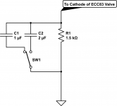
Yes, but don't do it that way. In your example, wire one of the 1uf caps permanently across the resistor, then just switch the other 1uf in and out. Remember, caps add in parallel, so two 1uf caps in parallel is the same thing as a 2uf cap. SO selecting between 1uf and 2uf is simple as adding a parallel cap to the other one.
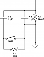
It will work but it will pop when you switch it in. SO wire a high value resistor, like 1 meg or 470k, across the switch. The resistor will keep the cap charged, but the high resistance will prevent th cap from acting in th circuit. Then the switch shorts across the resistor and that leaves the cap in the circuit.
It will work but it will pop when you switch it in. SO wire a high value resistor, like 1 meg or 470k, across the switch. The resistor will keep the cap charged, but the high resistance will prevent th cap from acting in th circuit. Then the switch shorts across the resistor and that leaves the cap in the circuit.
Many thanks, this is better and easier , nice one !
For the large resistor 'across' the switch - in parallel with it ? as shown in attachment.
Also do you know if it would be possible to use a three way switch to introduce 3 different capacitances to this part of the circuit - like 1/2 , 1 and 2 uF - also would it be worth doing ? Trying to use this first amp to test out sounds ..
Thanks again...
Attachments
yes^^^^
You will find some commercial guitar amps use the technique as part of their channel switching. Switch in some gain enlarging caps and maybe a voltage divider change elsewhere, and poof - channel switching.
If you are just experimenting, hey, let it pop. But you do want the large resistors in a finished product. Yes, your new drawing is exactly what I tried to describe in words. The same technique works when the caps are wide apart too, like 0.68uf and 25uf. hardwire the lower one, then just switch the larger one into parallel. In such cases, the smaller one essentially disappears into the larger one.
You will see this (switching in of extra bypass capacitance) used quite a bit in more recent designs. Most commonly the switch will be labelled "FAT" with the extra capacitance IN with the switch in the FAT position.
In a preamp with a Gain or Drive Control you may want the sound FAT at lower gain settings but with some bottom end knocked off (FAT switch OFF) at high gain settings to keep the sound from getting too muddy.
Cheers,
Ian
In a preamp with a Gain or Drive Control you may want the sound FAT at lower gain settings but with some bottom end knocked off (FAT switch OFF) at high gain settings to keep the sound from getting too muddy.
Cheers,
Ian
Hi guys!
Same situation here...
I got a amp (single-ended 6l6 based) with a two 12ax7s preamp section. Last week I decided to give it more options of different tones and gain. So I decided to install a DPDT switch (on-on) so that I can choose between different capacitors and resistors in the first triode of second preamp's tube.
I did it, but what I got now is a loud "pop" when changing the switch position, either way...
I'm attaching a image which illustrate the schematic and the layout I build for this sector.
Does anyone here know how I can get rid of this pop?
Remembering I've already installed a 470k across the switch, but I still got this annoying noise :/
Thanks!
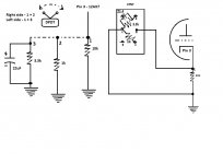
1) where is the 470k? I don't see it.
2) the anti pop resistor is not across the cap but across open switch contacts
3) what you show will pop like crazy, you are not only switching cathode caps in, but also different resistors in parallel with the original 10k one.
4) você é Brasileiro?
2) the anti pop resistor is not across the cap but across open switch contacts
3) what you show will pop like crazy, you are not only switching cathode caps in, but also different resistors in parallel with the original 10k one.
4) você é Brasileiro?
Hi, JMFahey!
1) Well, it wasn't shown in the schematic, couse this image illustrates what I did previously. Once I noticed that I had a "pop", I put one 470k resistor connecting dpdt pin 2 to the pin 4 as suggested here. Am I wrong?
2) Could you please tell me where this resistor must be correctly?
3) Yes! Is there any solution for it? This "poping" is due to the switching the cap in and out or to the different resistors in parallel? or both?
4) Sim! Sou brasileiro!")
1) Well, it wasn't shown in the schematic, couse this image illustrates what I did previously. Once I noticed that I had a "pop", I put one 470k resistor connecting dpdt pin 2 to the pin 4 as suggested here. Am I wrong?
2) Could you please tell me where this resistor must be correctly?
3) Yes! Is there any solution for it? This "poping" is due to the switching the cap in and out or to the different resistors in parallel? or both?
4) Sim! Sou brasileiro!
BYpass cap effect for your possible interest - see top graph.
The Valve Wizard -Cathode Follower
You may also use automated switching using a JFET in place of thE mechanical switch.
Cheers,
Ian
The Valve Wizard -Cathode Follower
You may also use automated switching using a JFET in place of thE mechanical switch.
Cheers,
Ian
- Status
- This old topic is closed. If you want to reopen this topic, contact a moderator using the "Report Post" button.
- Home
- Live Sound
- Instruments and Amps
- Switchable Cathode Bypass Capacitor for a Tube amp