Hey everyone, working on my first audio circuit and am questioning my layout. I don't have a breadboard to test the circuit before soldering so figured id come ask here before I solder everything up and end up with an AM receiver. Attached is the schematic I am going off, and the layout I have spent way too much time on, haha. Any input greatly appreciated!
EDIT: Please ignore my mislabeled 1K and 100K resistors
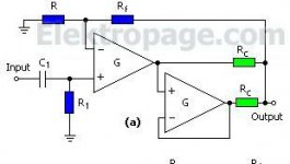
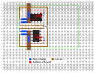
EDIT: Please ignore my mislabeled 1K and 100K resistors


Last edited:
Hi
A couple of things:
- You are missing the power supply connections, both in the schematics and on the layout.
- The input capacitor is not included in the layout
- If the opamps used (I assume standard 2 opamp layout btw) are anything like a modern not-very-slow opamp you will need decoupling capacitors either between the power supply pins or from power supply pins to ground - without the amplifiers will very probably act like transmitters
- Not really important: but usually one would aim to make the two sides of the layout symmetrical. The 90 degree difference in opamp orientation will at least once make you measuring on the wrong pin
- I would usually try to have the input ground and signal placed closer to each other: connecting a shielded cable to your layout will make the wires cross the output.
Cheers,
Martin
In my haste I forgot to mention that I hid power for clarity. Input cap is the brown vertical thing labeled "IN". Also plan on bypass caps on V+ and V-, just not there yet. OPA1612 on dip-8 board.
This to me is more symmetrical because input and outputs are symmetrical. I tried to lay it out on protoboard like 100 times and this is what I kept coming back to as it just makes more sense to me.
After some reading, I went with the "every ground has its out path" route, so those four resistors connected to ground all have their own path to VG. Did I misunderstand? Could you elaborate on what you mean about connecting a shielded cable?
Oh, I see what you are saying about the cable. Was a draw back I was willing to make. Building this thing out of random meh parts with a few "good" stuff mixed in. Basically I was bored one day and put together a resister divider VG board with way too many caps (pics attached) and went from there. Nothing is really ideal just trying to figure out how to go from schematic to layout better, cause to get to that nice looking halfway decent layout on perfboard from the schematic took way too long haha.
With the supply bypass caps, would it be better to do V+/V- to ground or a cap across pins 4/8? Or is it six one way half dozen the other?
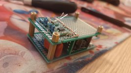
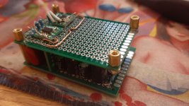
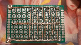
With the supply bypass caps, would it be better to do V+/V- to ground or a cap across pins 4/8? Or is it six one way half dozen the other?


Ok, let me start with the bypass caps.
There seems to be some debate on whether one cap between power rails or one from each power rail to ground is the best.
I for sure do not have the definite answer to this, but: all the opamps I've used works well with one bypass, but I've seen comments about certain opamps needing the 2 caps for stability.
Do remember though that the bypass caps not only stops an opamp from oscillating, but also bypasses the noise from the power supply.
I you have a power supply with a lot of HF-noise (like some SMPS'es), the 2 cap bypass will actually bypass the noise into ground, resulting in a noise current in the ground and according to Murphy this will always be through the same wires as the audio signal.
This is the primary reason that I personally prefer the bypass with one cap between power rails.
But, please note this is not the definite answer
Grounding: In general you do not need to have every single component needing connection to grounding having its own path (in some of the circuits I've designed and build, there may have been 50-100 components needing a ground connection - having that same number of wires to the power supply ground would have been challenging).
I think you should read your quoted recommendation as a recommendation for "groups of functionality" - like multiple circuit boards or multiple seperate amplifiers.
In your case I would definitely tie the input resitor and the one from the -input together. The speaker (headphone) connection could very well have its own connection to ground (this would be recommended for a larger amplifier).
Cheers,
Martin
The way I read it, star grounding would help keep the chances of me building a ground loop into it, so hence my reason for it (this is technically my second attempt, my first attempt at going from schematic to perfboard I did before my too much reading, and, well, I made the worst sounding AM radio of all time haha (pic attached)).
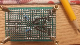
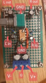
All grounds would be connected to AGND, so the input ground are connected, just not closely. With there really only needing the four paths to ground, this hopefully works and looks pretty to boot. I'm also under the impression that having the grounds around the circuit like that helps a bit with shielding, as this will be in a plastic case with no chassis GND. If this were something with alot of connections to ground, and I actually had the knowledge to do perfboard or pxb layout, I would almost certainly just use a continuous large ground plane. As for the headphone ground, place it as close to VG start as I can? I.e. right after the caps, or do you think to AGND would be fine?
Thanks for your time and expertise,
Jake
Ok
Having ground covering as much as possible will tend to reduce the amount of induced noice (in some cases being radio signals).
But nothing beats putting the circuit in a shielding box.
I am not sure if I interpret you suggestion about the speaker wire - but in short: Dont let the current from the speaker share the input ground connection.
Think of this as: the larger current from the speaker will generate a voltage differential over the ground connection and this signal should not come in series with the input ground.
This will quite often result in instability of the amplifier.
Cheers,
Martin
- Home
- Amplifiers
- Headphone Systems
- Help with op amp layout