Note: This is a split-off from
lingDAC - cost effective RBCD multibit DAC design
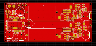
As the PhiDAC hex doesn't drive headphones directly I designed this headphone amp to partner it. Its very simple and has low BOM cost, using the JFET input AD744 with a classA SE output stage. A couple of prototypes have been built and here is the first PCB layout. Would there be any interest in kits of this too? PCB size is 10 * 4.5cm - JLCPCB currently has a special which gets us 5 PCBs for 5RMB, including shipping. Normally shipping alone costs more than this 😀
lingDAC - cost effective RBCD multibit DAC design
As the PhiDAC hex doesn't drive headphones directly I designed this headphone amp to partner it. Its very simple and has low BOM cost, using the JFET input AD744 with a classA SE output stage. A couple of prototypes have been built and here is the first PCB layout. Would there be any interest in kits of this too? PCB size is 10 * 4.5cm - JLCPCB currently has a special which gets us 5 PCBs for 5RMB, including shipping. Normally shipping alone costs more than this 😀
Attachments
Here's the schematic, its about 90% the same as PhiDAC hex minus the DAC part. Yes it runs on the same power supply as PhiDAC hex (12-15V).
Btw some of the resistor values aren't correct, I'll update and repost in a day or so.
I have used a similar output stage. The NE5534 has a compensation pin also tracking the output I believe at about -0.6volts. What do you normally design for in terms of a headphone load impedance?
I designed this one to suit my HD6XX which are 300ohm. It works great with them with 0dB of gain from PhiDAC hex. I also plan to try it with some gain on my DT880s (600 ohm). It can drive lower impedances but will be quite inefficient, even by the (dismally low) standards of SE classA.
PhiAMP schematic
Here's the PhiAMP schematic which was attached to a post which got moved to the Vendor's Bazaar.
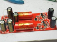
This schematic represents the first prototype of PhiAMP - I built up two and my friendly beta-tester has also built one. Based on a couple of minor issues with the initial builds there's a rev2 PCB coming back today with fixes.
This amp is designed primarily for higher impedance headphones - ones which likely need voltage gain from a DAC. Examples are HD6XX and DT880/990. I find HD6XX works great with unity gain from a 2VRMS source - in this configuration it runs fine from a 12V supply, same as PhiDAC hex. My 600ohm DT880s want more drive though which necessitates a higher supply voltage. The rev2 makes setting a higher supply easier as it uses a zener diode for reference rather than LEDs. Choosing various colour LEDs for particular voltage drops is rather a crapshoot, a zener is far more predictable.
The second issue is related to grounding - with the DAC and AMP running from the same supply the ground connection can carry noise currents if the supply powering both is noisy. To circumvent this the grounding on rev2 is configurable, depending on whether its powered by the same supply as the source, or not.
Once I've tested out rev2 I'll post up the schematic.
Here's the PhiAMP schematic which was attached to a post which got moved to the Vendor's Bazaar.
This schematic represents the first prototype of PhiAMP - I built up two and my friendly beta-tester has also built one. Based on a couple of minor issues with the initial builds there's a rev2 PCB coming back today with fixes.
This amp is designed primarily for higher impedance headphones - ones which likely need voltage gain from a DAC. Examples are HD6XX and DT880/990. I find HD6XX works great with unity gain from a 2VRMS source - in this configuration it runs fine from a 12V supply, same as PhiDAC hex. My 600ohm DT880s want more drive though which necessitates a higher supply voltage. The rev2 makes setting a higher supply easier as it uses a zener diode for reference rather than LEDs. Choosing various colour LEDs for particular voltage drops is rather a crapshoot, a zener is far more predictable.
The second issue is related to grounding - with the DAC and AMP running from the same supply the ground connection can carry noise currents if the supply powering both is noisy. To circumvent this the grounding on rev2 is configurable, depending on whether its powered by the same supply as the source, or not.
Once I've tested out rev2 I'll post up the schematic.
Attachments
Here's the PhiAMP schematic which was attached to a post which got moved to the Vendor's Bazaar.
This schematic represents the first prototype of PhiAMP - I built up two and my friendly beta-tester has also built one. Based on a couple of minor issues with the initial builds there's a rev2 PCB coming back today with fixes.
This amp is designed primarily for higher impedance headphones - ones which likely need voltage gain from a DAC. Examples are HD6XX and DT880/990. I find HD6XX works great with unity gain from a 2VRMS source - in this configuration it runs fine from a 12V supply, same as PhiDAC hex. My 600ohm DT880s want more drive though which necessitates a higher supply voltage. The rev2 makes setting a higher supply easier as it uses a zener diode for reference rather than LEDs. Choosing various colour LEDs for particular voltage drops is rather a crapshoot, a zener is far more predictable.
The second issue is related to grounding - with the DAC and AMP running from the same supply the ground connection can carry noise currents if the supply powering both is noisy. To circumvent this the grounding on rev2 is configurable, depending on whether its powered by the same supply as the source, or not.
Once I've tested out rev2 I'll post up the schematic.
I'm using noDac with your LPF so can't reach 2VRMS source, any inputs to adapt the headphone amp?
Are PCB availables?
TIA
Felipe
I'm using noDac with your LPF so can't reach 2VRMS source, any inputs to adapt the headphone amp?
There are two resistors (per channel) which set the gain so yes you can cater for lower level sources.
Are PCB availables?
Rev2 PCBs just came in last night, once I've built a few and checked performance then yes, sure. Well, gerbers anyway.
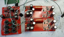
I also plan to try paralleling this amp - if two or three can be paralleled then the output power could be increased enough to drive planars. I have some Fostexs here to run them into.
Paralleled PhiAMPs
Early days yet but the way the Fostex's are sounding with this configuration completely distracts me from how uncomfortable they are to wear.😎
The rev2 board incorporates a 'ground lift' resistor which makes single-ended connections between DAC and AMP much less troublesome. Notice the ground to the headphones needs to be at the DAC's star ground for best performance.
Attachments
Schematic and gerbers for PhiAMP headphone amp
The third edition of 'PhiAMP' has added configuration links (0R resistors) to allow it to operate either as a plain stereo amp, a paralleled mono amp or a bridged mono amp. Otherwise its the same design as previous versions.
With the components shown the output stage bias level is about 50mA - given its an SE classA the bias is equal to the maximum output current. Thus the minimum impedance that can be driven to full level (2VRMS) is around 60ohm. Paralleling effectively doubles the current, allowing loads down to 30ohm. Bridging doubles the voltage to 4VRMS - the minimum impedance then is 120ohm. Lower impedances can be driven - the amp is still stable - just the output swing will be clipped by limited current in the positive direction before the full output voltage is reached.
Attachments
- Home
- Amplifiers
- Headphone Systems
- PhiAMP SE ClassA headphone amp