Hi guys,
I am still new in this forum,
and may have a kind of advanced question here:
I have a pair of Monoprice M1060C headphones,
which I really love to drive loud.
The thing is: to drive these to their max spl,
about 1W is needed, and they can even withstand 5W of power for a short amount of time.
To the point: I would like to drive them with a portable Sound Blaster E5, since this is a affordable device with unique features (SPDIF and bluetooth aptX-HD and a TPA6120A2 chipset).
The TPA chipset itself has proven to drive the M1060C to 80-90% of my desired volume (which is ok for me for mobile use) with a cheap chinese headphone amp pcb.
However, Creative did a really bad job implementing the the TPA chip, which means it is generally sounding bad above 60-70% of the volume and starts clipping pretty early compared to the cheap china pcb (with the same chipset, but beefy power supply). My best guess is that the TPA does not have the right power supply and therefore the voltage starts to drop, leading to bad sound and clipping.
Hopefully giving the TPA enough power will enable it to deliver the full and clear sound that the chipset is able to.
Thats why I want to find a way to improve the circuit, f.e. by with exchanging the main dc power converter (or adding a second one of the same) or/and adding caps.
I dont really care about higher power usage and shorter battery life.
I have the equipment and skills to solder any of the needed parts, so this is not a problem. Only problem is: Electronically speaking, I only have basic knowledge, this is where I hope to get some input from the brave diyaudio community")
My research so far:
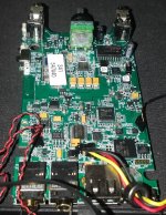
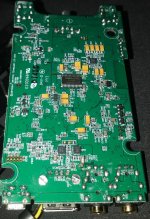
One of the components is a TPS65131, a the dc-dc-voltage converter, which should be the main power source.
The TPA VCC+/- input pins have about 20V, in higher volume settings and higher bass extent it jumps down to 13-15V (which seems to support my "unsufficient power supply" thoughts).
I have put some attachments with photos of the pcb.
I am thankful for every tip.
hackbart
I am still new in this forum,
and may have a kind of advanced question here:
I have a pair of Monoprice M1060C headphones,
which I really love to drive loud.
The thing is: to drive these to their max spl,
about 1W is needed, and they can even withstand 5W of power for a short amount of time.
To the point: I would like to drive them with a portable Sound Blaster E5, since this is a affordable device with unique features (SPDIF and bluetooth aptX-HD and a TPA6120A2 chipset).
The TPA chipset itself has proven to drive the M1060C to 80-90% of my desired volume (which is ok for me for mobile use) with a cheap chinese headphone amp pcb.
However, Creative did a really bad job implementing the the TPA chip, which means it is generally sounding bad above 60-70% of the volume and starts clipping pretty early compared to the cheap china pcb (with the same chipset, but beefy power supply). My best guess is that the TPA does not have the right power supply and therefore the voltage starts to drop, leading to bad sound and clipping.
Hopefully giving the TPA enough power will enable it to deliver the full and clear sound that the chipset is able to.
Thats why I want to find a way to improve the circuit, f.e. by with exchanging the main dc power converter (or adding a second one of the same) or/and adding caps.
I dont really care about higher power usage and shorter battery life.
I have the equipment and skills to solder any of the needed parts, so this is not a problem. Only problem is: Electronically speaking, I only have basic knowledge, this is where I hope to get some input from the brave diyaudio community
My research so far:
One of the components is a TPS65131, a the dc-dc-voltage converter, which should be the main power source.
The TPA VCC+/- input pins have about 20V, in higher volume settings and higher bass extent it jumps down to 13-15V (which seems to support my "unsufficient power supply" thoughts).
I have put some attachments with photos of the pcb.
I am thankful for every tip.
hackbart
Attachments
Last edited: