Hi All.
I’m busy building the final output opamp buffer stage for my mono headphone amp.
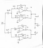
I have managed to build the output stage using opamps configured as non inverting buffers and using 1ohm current sharing resistors to effectively parallel the two sections of a dual opamp.
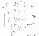
I however only realized afterwards that I need to use an inverting buffer topology as my preceding mixer/ gain stage is inverting also.
This will give me absolute phase from input socket to output socket.
What are the drawbacks of using the inverting topology over the non inverting topology? If any.
I can see that the parts count is higher and that I would have to increase the input coupling cap value.
I have attached the two circuits. Sorry for the jpegs.
Thanks in advance.
I’m busy building the final output opamp buffer stage for my mono headphone amp.
I have managed to build the output stage using opamps configured as non inverting buffers and using 1ohm current sharing resistors to effectively parallel the two sections of a dual opamp.
I however only realized afterwards that I need to use an inverting buffer topology as my preceding mixer/ gain stage is inverting also.
This will give me absolute phase from input socket to output socket.
What are the drawbacks of using the inverting topology over the non inverting topology? If any.
I can see that the parts count is higher and that I would have to increase the input coupling cap value.
I have attached the two circuits. Sorry for the jpegs.
Thanks in advance.
Attachments
The primary disadvantage that I can see for inverting is that the gain is only as close to -1 as the resistors allow so you'll need close tolerances for the 39ks. In non-inverting the unity gain doesn't depend on resistor tolerances so your individual elements are much better matched.
The inverting topology inherently comes with a tradeoff between input impedance and noise performance for a given gain, through the choice of resistor values (and interaction of those with opamp types).
It does, however, also have its upsides - for example, being able to implement negative gain.
BTW, better use just one pair of feedback resistors for both parallel opamps, this will elimiate issues related to their inevitable tolerances. Keep the (-in) node nice and compact though.
It does, however, also have its upsides - for example, being able to implement negative gain.
BTW, better use just one pair of feedback resistors for both parallel opamps, this will elimiate issues related to their inevitable tolerances. Keep the (-in) node nice and compact though.
Inverting topology is free from common-mode distortion, which sometimes is an issue (large signal swings principally). Inverting amps impose a load on the preceding stage, this can be an issue if its driven from a filter/tone network for instance - increasing the resistor values will decrease the loading on the previous stage, but increase the noise...
BTW, better use just one pair of feedback resistors for both parallel opamps, this will elimiate issues related to their inevitable tolerances. Keep the (-in) node nice and compact though.
Erm, that doesn't sound possible - they will fight each other for control.
You can use one opamp in inverting mode and the other as a follower from it, then sum the outputs.
If I may, you might want to look at the LT1010 (or similar) instead. It's a power booster, good up to about 100 mA and designed to work either stand-alone or, as you would use it, inside the feedback loop of an inverting op-amp.
Switching to an LT1010 would get rid of three of the op-amps, gives you the inverting configuration you want, removes the problem of matching the resistors, doubles the available output current, and does it all without adding extra distortion. The only down-side is they cost a bit more than an op-amp, about $6 (US) per IC.
Jonathan
People have been merrily stacking TL072s (with their several hundred ohms worth of output impedance) for years now, so it does basically work just fine... types designed for headphone driving are likely to require the odd ohm of external current sharing resistance, of course, but the OP already had that. It's not really all that different from paralleled transistors, really.Erm, that doesn't sound possible - they will fight each other for control.
When using two independent pairs of feedback resistors, you have both opamp offset variation and resistor tolerances to contend with, so chances are you'd need higher value current sharing resistors than when sharing a common feedback network.
- Status
- Not open for further replies.
- Home
- Amplifiers
- Headphone Systems
- Headphone amp output buffer stage help