I did a bunch of forum searching but was still not finding the answer I needed.
What I'm trying to do is elevate the voltage at the Source of the IRF610. I'm using a LM337 as a CCS for the biasing but when I built up the circuit I only get a couple volts max at the where the output cap connects to the Mosfet Source when I would like 6-7 volts.
Please help me learn where I am going wrong with this 🙁
Any other help is also appreciated!
Attachments
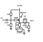
What I'm trying to do is elevate the voltage at the Source of the IRF610.
I'm using a LM337 as a CCS for the biasing but when I built up the circuit
I only get a couple volts max at the where the output cap connects to the
Mosfet Source when I would like 6-7 volts.
Make the resistor variable and adjust it for the source voltage needed.
You need at least 5Vgs to get current going in the IRF610, so you may need
to adjust the gate bias voltage. Is the LM337 on a heat sink?
You can also use the LM317 (which is better), if you flip it.
Last edited:
Hey, thanks for the quick response. Which resistor did you mean? The only one that would make sense to me is the 1M resistor connecting the 12VDC and Mosfet Gate. Is that the one you mean?Maybe make the resistor variable and adjust it for the source voltage needed.
Is the LM337 on a heat sink?
You can also use the LM317 if you flip it.
EDIT: yeah, the LM337 is screwed to the chassis top plate, so plenty of heatsinking (main reason I chose the LM337 is because the tab is at ground potential in this circuit)
Last edited:
The only one that would make sense to me is the 1M resistor connecting
the 12VDC and Mosfet Gate. Is that the one you mean?
Since you need 5V or more Vgs, the gate bias resistors may need
to be adjusted make the gate voltage enough, if you want the output
to be centered (around 6-7V). Try making the upper 1M to be 200k instead.
Last edited:
K, I'll try that and report back 🙂Since you need 5V or more Vgs, the gate bias resistors may need
to be adjusted make the gate voltage enough, if you want the output
to be centered (around 6-7V). Try making the upper 1M to be 200k instead.
the LM337 is screwed to the chassis top plate, so plenty of heatsinking
(main reason I chose the LM337 is because the tab is at ground potential in this circuit)
Ok, that's reasonable. Use some thermal paste though.
K, I'll try that and report back 🙂
Or use a 100k or 1M pot between 12V and ground, with the wiper to the grid.
Adjust the pot for centered DC output voltage.
Last edited:
I'll probably try this if I don't have any luck with my resistors I have in my bin 🙂Or use a 100k or 1M pot between 12V and ground, with the wiper to the grid.
Adjust the pot for centered DC output voltage.
I'll probably try this if I don't have any luck with my resistors I have in my bin 🙂
Start the pot at half resistance to avoid surprises.
I'll probably try this if I don't have any luck with my resistors I have in my bin 🙂
You may need a bit more than 12V for the supply for this circuit,
perhaps more like 15V. If you do get it working with the pot,
measure and replace the pot with two metal film resistors.
Last edited:
I have done basically all of these suggestions now and am still having some issues... Starting to think I have a bad batch of Mosfets.
Using an LM317 CCS on the source of the IRF610PBF (ordered these on Mouser), I have 250mA in current and the measured voltages it are: Drain 13.6V, Gate 6.8V, Source 2.2V
It seems super weird to me that the voltage between the gate and source is so much. Any ideas?
Using an LM317 CCS on the source of the IRF610PBF (ordered these on Mouser), I have 250mA in current and the measured voltages it are: Drain 13.6V, Gate 6.8V, Source 2.2V
It seems super weird to me that the voltage between the gate and source is so much. Any ideas?
No, that's completely expected. Vgs = 6.8 - 2.2 = 4.6V. That's roughly the plateau voltage of the device. Gate voltages vary +/-1V or so, so different devices can have pretty different bias points.I have done basically all of these suggestions now and am still having some issues... Starting to think I have a bad batch of Mosfets.
Using an LM317 CCS on the source of the IRF610PBF (ordered these on Mouser), I have 250mA in current and the measured voltages it are: Drain 13.6V, Gate 6.8V, Source 2.2V
It seems super weird to me that the voltage between the gate and source is so much. Any ideas?
The plateau in the gate charge/voltage graph is where the conducting channel forms (which soaks up charge to do).
Remember that this sort of MOSFET is designed to be switched, and designed for the gate-source voltage to be 0V for off or +12V for on state.
No, that's completely expected. Vgs = 6.8 - 2.2 = 4.6V. That's roughly the plateau voltage of the device. Gate voltages vary +/-1V or so, so different devices can have pretty different bias points.
The plateau in the gate charge/voltage graph is where the conducting channel forms (which soaks up charge to do).
Remember that this sort of MOSFET is designed to be switched, and designed for the gate-source voltage to be 0V for off or +12V for on state.
Thank you! This is incredibly helpful info. I'll make some changes and report back 🙂
With 6 volts in the source, the maximum excursion of the output signal would be at best 1,7 Vpeak, since the LM337 minimally requires a difference of 3 Volts between its input and output pins. Being able to find up to 1,3 Volts maximum on the terminals of the resistance of 5 ohms, would be the mentioned excursion of 1,7 Vpeak. This suggests that the probable 260 mA circulating from the drain to the source would not be necessary, if the headphones are of a minimum impedance of 32 ohms. Perhaps, a resistor of 18 ohms x 1/2 Watt instead of that of 5 ohms, would be more than enough for what can occur within a linear operation 😉.
Tip: increase the gate voltage to about 10 Volts approx. Replace the upper 1 Mohm resistor by 180 Kohm resistor.
Best regards
Tip: increase the gate voltage to about 10 Volts approx. Replace the upper 1 Mohm resistor by 180 Kohm resistor.
Best regards
Last edited:
- Status
- Not open for further replies.
- Home
- Amplifiers
- Headphone Systems
- Need Help with single ended Mosfet Source Follower biasing in headphone amp (IRF610)