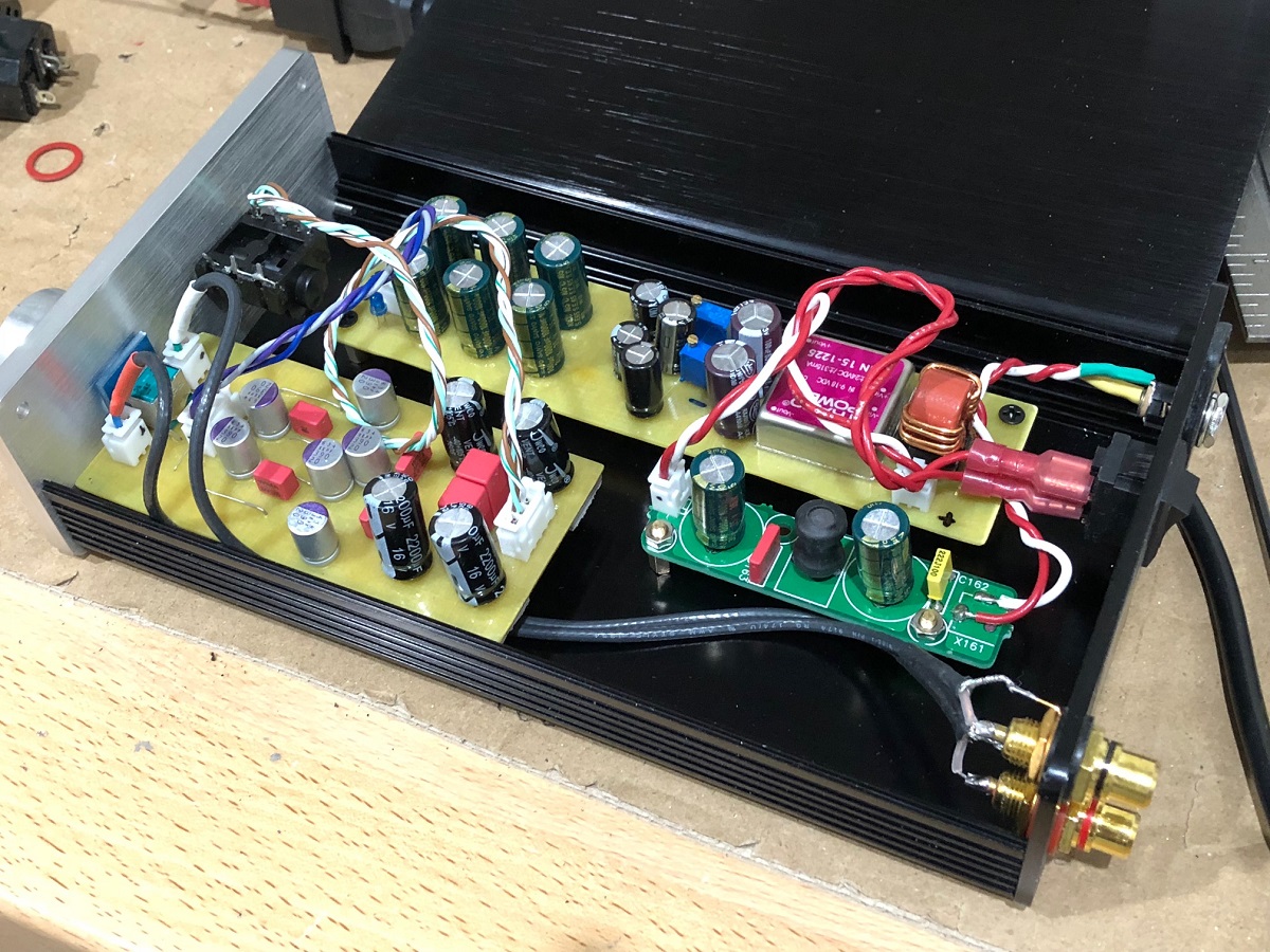
Just finished soldering a pair of simple op amp with BUF634 mono headphone amplifiers.

Distortion is around 0.001% using NE5534. The sound is clean and precise without being overly analytical. I'll experiment with other op amps over the weekend.
I've attached Eagle files if anyone else wants to build their own.
Distortion is around 0.001% using NE5534. The sound is clean and precise without being overly analytical. I'll experiment with other op amps over the weekend.
I've attached Eagle files if anyone else wants to build their own.
Attachments

Before you start rolling opamps, why not clean up the opamp supply with a couple of LC filters? Looks like you have the buffer and the opamp sharing the very same rails (though I've not checked the PCB).
Before you start rolling opamps, why not clean up the opamp supply with a couple of LC filters? Looks like you have the buffer and the opamp sharing the very same rails (though I've not checked the PCB).
You are correct, they share the same supply, but they have separate capacitors. I wanted a small, simple board. What values would you suggest for the LC filter if I make bigger boards??
I ran a quick sim and found 150uH with a total of 0.5ohm damping into 1000uF Nichicon HZ (chosen for lowest ESR) gave a critically damped response.
The inductors I use are SMT types - SLF7045 by TDK. The 150uH in that range is 0.34ohm so needs 0.15ohm damping resistor in series.
If you need a through-hole style, Mouser has these which look a good fit : RLB0712-151KL Bourns | Mouser
The inductors I use are SMT types - SLF7045 by TDK. The 150uH in that range is 0.34ohm so needs 0.15ohm damping resistor in series.
If you need a through-hole style, Mouser has these which look a good fit : RLB0712-151KL Bourns | Mouser
Would you like to try something a times better?
😉
Sure, what do you suggest?
I ran a quick sim and found 150uH with a total of 0.5ohm damping into 1000uF Nichicon HZ (chosen for lowest ESR) gave a critically damped response.
Thank you abraxalito, I'll give that a try 😀
Sure, what do you suggest?
Ok. Let’s try to optimize.
First of - noninverting must die. Modern opamps are a way better than their girlhood predecessors, but there are no way to compensate common mode error which are nonlinear with common mode itself. So - only inverting.
Second of - BUF634 must die. Just check simplified schematic. TI’s engineers put some input resistance for stability issues, but remember - are there a way to put true resistance in a monolitic techprocess? Noway, that is not resistance at all - this is biased diode with at least 7-10% THD. This is because TI doesn’t show openloop buffer THD. Drop it in a garbage bin, use older sophisticated brother LMH6321 and put something like 1k resistance at the input. It will provide you not only with stable and powerful OPS, but even with a some kind of load protection, since buffer needs some input current.
Next - feedback depth. Just a bruteforce, as high as possible. Use higher grade noncompensated high-GBW opamp, AD8067, LM7171, LT1222, THS4021.
Next - supply decouple. Use at least two pairs of modern solid-polymer capacitors per rail for each OPS chip, say 330-470 uF. Doing this will provide you with smallest supply resistance ever. Add some simple CRC-filter with first 1 mF cap for good 50/60 Hz damping and excluding signal frequencies in mains. Loop all signal currents strictly at board.
Next - mains and ground decouple. Strictly use as small as rated El trafo with sectioned windings. This will provide you with ~20-30 pF parasitic capacitance.
Next - gain and noise. Since we’re inverting input resistance must be as low as possible, but lowish one’s will load previous stage (say DAC), so i’ll prefer to use 2k. Not so low for DAC THD raise, not so high for noise raise. Rebuild your resistance-ladder volume regulator for that load resistance or use linear-scale 10k potz, both will provide you with nice log-scale regulation a way better than log-potz. Try not to raise gain, it’s better to provide two-three optimised versions for different headphones, say -0,2-0,5x for high-sensitivity low-resistance, 1-2x for high-sensitivity high-resistance and ~10x for low sensitivity high-resistance ones.
Next - output common-mode noise or capacitive load decouple. Since your amp becomes very high frequency’ed it’s better to shorten all connections. Best way is to put it inside or over/near headphones cup. This will anyway exclude wire-coloration due to non-zero wire resistace and greatly reduces common mode noise picking due to short connections. There are not so much heat from class-AB OPS. If you’re limited in that “naughty handcrafting” - provige common mode choke. It’s better to wire different ground wire to each speaker with dedicated choke at each channel, but if you’re limited at three-wire common-ground connection use Murata 78602/3jc or ...2jc with 1-6 connectors for ground wire.
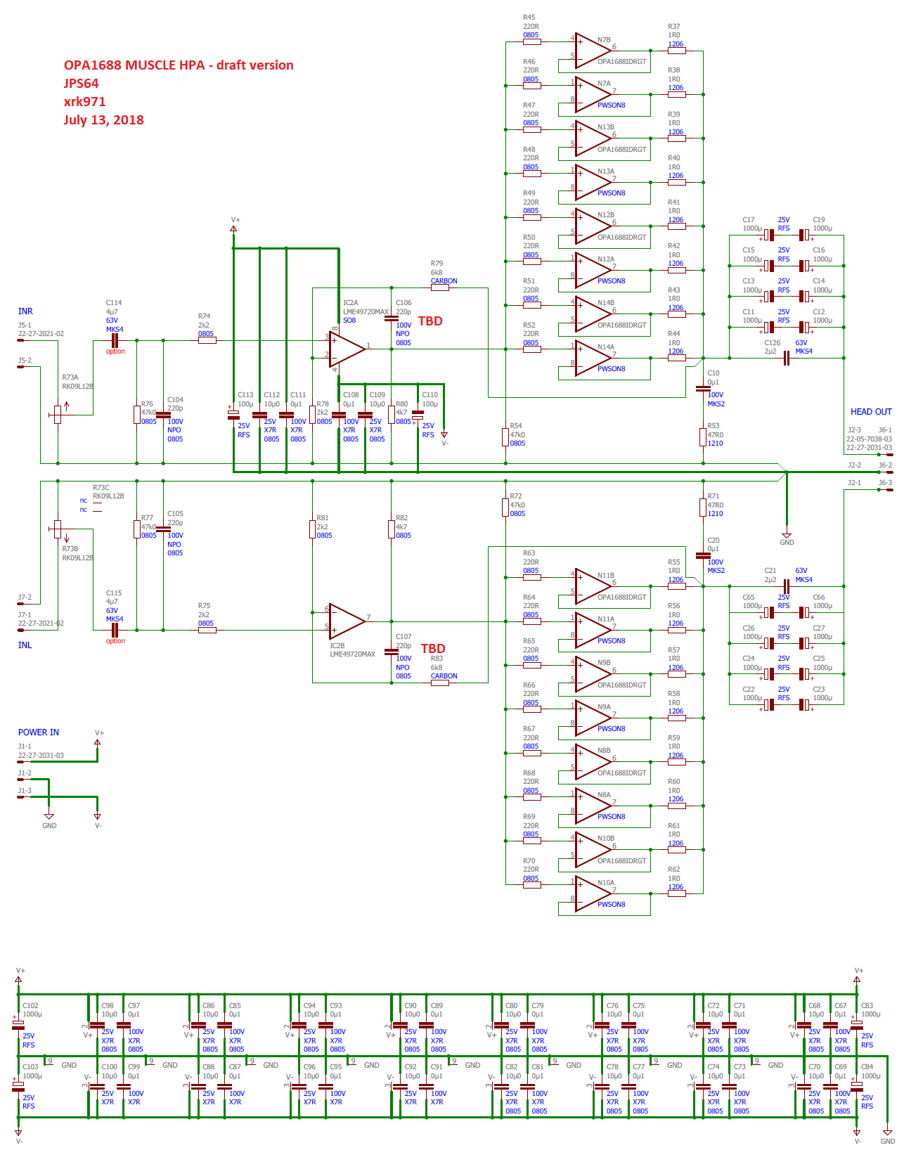
Of course, some SCH attached.
Gain=-1, over 70 dB feedback depth at 20 kHz.
Keeping in mind order of -60 dB of buffer THD and adding 70 dB feedback we will pick near -130 dB distortion figures.
Attachments
Last edited:
Won't using the LM7171, like in the schematic above, without a input coupling cap result in high DC offset as well as DC on the volume pot's wiper?
Input bias current is quite high for a lot of the better bipolar op-amps.
Input bias current is quite high for a lot of the better bipolar op-amps.
Lots of good recommendations Abrax. But why so down on the OP’s titled opamp buffer? I suppose the LME49600 could be used - about same price and have 500mA and less distortion. But many of those designs floating around.
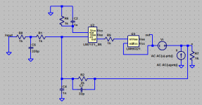
I recently used an OPA1688 for voltage gain and used a pair of OPA1688 in parallel for the buffer. It’s working out really well. With 18v rails and supply decoupling via 10uF and 100nF x7r’s right on pins basically it is very quiet and sounds great.
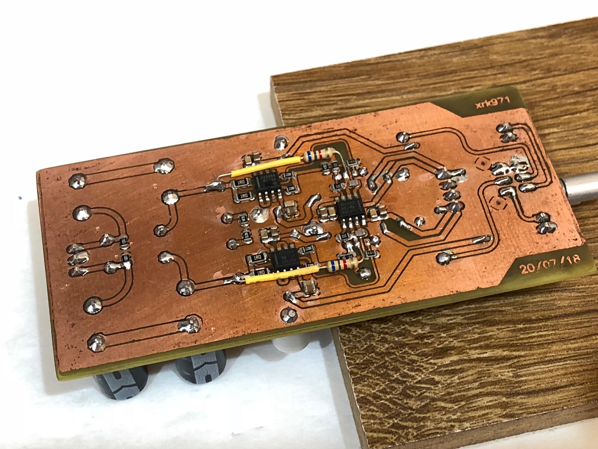
Top view (using low ESR OSCON rail caps):

One can take it an extreme of 8 in parallel:
It worked so well I had to box it up and it’s in constant use now. Great as a Preamp too.
I recently used an OPA1688 for voltage gain and used a pair of OPA1688 in parallel for the buffer. It’s working out really well. With 18v rails and supply decoupling via 10uF and 100nF x7r’s right on pins basically it is very quiet and sounds great.
Top view (using low ESR OSCON rail caps):
One can take it an extreme of 8 in parallel:
It worked so well I had to box it up and it’s in constant use now. Great as a Preamp too.
Last edited:
result in high DC offset
Ok, being scared by dozens ov uV typical offset we could use AD8067 with typical less than a pA input bias current.
😉
Input bias current is quite high for a lot of the better bipolar op-amps.
You know first hand we talk about very different parameters. Of course i will exchange that DC offset for high feedback depth through audioband. One could prefer to keep null grounded.
I know there are plenty of op amp based variants amps out there. I was attracted to the simplicity of this combination, and wanted to give it a try.
I'm currently putting together a through-hole version of The Wire, will post more when it's ready.
I'm currently putting together a through-hole version of The Wire, will post more when it's ready.
Yas BesPav, thank you for a really good post!
But there is some stuff here, that I don't understand.
In theory an inverting, buffered OpAmp circuit should be very simple (?) as in the picture below:

In your opinion, what kinds of downfalls would this way of wiring it up have?
But there is some stuff here, that I don't understand.
In theory an inverting, buffered OpAmp circuit should be very simple (?) as in the picture below:
In your opinion, what kinds of downfalls would this way of wiring it up have?
Your input impedance is only 1 kOhm. Probably fine for any device that can drive headphones by itself (DAP, soundcard etc.), but still lower than what's considered normal in the hi-fi world (which would be 10k and up).In theory an inverting, buffered OpAmp circuit should be very simple (?) as in the picture below:
In your opinion, what kinds of downfalls would this way of wiring it up have?
Noise gain of an inverting circuit also is 1 higher than signal gain, which becomes rather noticeable by the time you want lowish gains and highish input impedance.
Last edited:
Yas BesPav, thank you for a really good post!
Nothing for!
In your opinion, what kinds of downfalls would this way of wiring it up have?
Let’s analyze.
1. Comparatively low input impedance will result in lower noise due to straight impedance lowering and higher distortion due to higher loadind of previous stage. I’ll prefer 2k, too low for noise and too high for previous module.
2. Gain of -10 is too high for headphone use, in my opinion, especially with typical opamp-level supply not more than 15-18 V. High-impedance and low sensitivity headphones could demand higher signal levels with that or even higher gain, but they also demands higher signal voltage which couldn’t be achieved with opamp-level supply. Maybe fully-differential opamp like THS4131 could be used in this case, doing this will double output voltage.
3. Noninverting input straight on ground will lower CMRR, but in case of high input bias current could lower output offset.
4. Feedback circuit shown could be used with opamp stable at gain of >~10. But if you doesn’t need so high gain and prefer to lower distortion up to 20-30 dB there could be used low gain of -1 with uncompensated high-GBW opamp. So all of excessive gain of uncompensated opamp will be straightly exchanged to higher feedback depth and lower distortion figures, but demand some stabilization circuitry like shown.
- Status
- Not open for further replies.
- Home
- Amplifiers
- Headphone Systems
- Simple op amp + BUF634 HPA