Hi, I'm designing a portable device that will have both a headphone and speaker amp. The speaker amp will be a simple PAM8403 module, the headphone amp is based on OPA1688 opamps, similar to a CMoy design.
The question here is how I turn off the speaker amp when I plug the headphone in. For the moment I am thinking about leaving the headphone amp on at all times since the quisecent draw is negligeable. The speaker amp though needs to be disconnected when the plug is inserted. The PAM8403 chip has a shutdown pin, that is internally pulled high (can be left floating), and when connected to GND shutdown is active.
Using a 4-input switched headphone connector and using the extra switched pins for sensing the plug was the idea, but I come up empty with working ideas.
Help appreciated!
The most common solution is what I have here. Problem is that I do not want to introduce an RC filter on my output. The OPA1688 has virtually no DC on output, so no caps there in my design. And with that this design fails. New ideas?
Last edited:
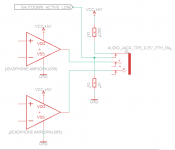
Idea for solution. Using a 6-pole plug that have a switch for the MIC position on a plug. It is not used for plain audio so I can use the innermost tab for my HP sensing. When plug is out, shutdown is pulled up and not active. When plug is in the circuit is cut, and shutdown is connected to ground over a 1K resistor. Should be enough to pull down shutdown to below 0.7V which is logic low I hope.
I was a bit worried for DC voltage from the pull-up being input to the HP momentarily when inserting plug, as the switch tab runs over the plug. But with 100K there will be no more than 15mV over a 300 ohm phone. And that DC burst is only momentarily.
Is my thinking correct?

I was a bit worried for DC voltage from the pull-up being input to the HP momentarily when inserting plug, as the switch tab runs over the plug. But with 100K there will be no more than 15mV over a 300 ohm phone. And that DC burst is only momentarily.
Is my thinking correct?
Attachments
I'll answer this myself. ")
The most simple solution is to use a non-switched 4-pole (TRRS) connector. That 4:th pole is normally used for a microphone connection, but we will just wire that ring connector directly to the shutdown pin. The connector should be used with a standard stereo plug, without mic ring.
When the plug is inserted the mic ring input will be shortcircuited to ground, hence the PAM8403 will be disabled.
When plug is removed the mic ring will be unconnected, the signal will be floating, and that is interpreted as PAM8403 enabled.
Simple as that. I'll build this tomorrow and test, and in case this don't work as intended I'll update this. Otherwise this is it.
Interesting little problem. However, I am confused: How did the previous arrangement (post #1) even work to begin with? These headphone jacks tend to have their switching contacts closed when unplugged and open when plugged in, thereby allowing to disconnect a (small) speaker. That would be exactly the opposite of what's needed here, IOW it would mute when unplugged, and you'd need an inverter (1 whopping transistor + maybe a cap for debounce) to make it work as intended.
Using one of the last contacts in a TRRS jack is a clever little solution but may be slightly noisy upon insertion. This is why I plug in my headphones before turning on my Dell notebook - granted, the culprit there is the mic bias voltage, and that has a good bit more "oomph" than what you're probably going to need for the internal pull-up (documentation of which appears to be sorely lacking). Sparing e.g. two transistors for a little buffer and going rather high in impedance (1 megohm-ish) may be advisable. Due to these side effects, I would slightly prefer the original switching jack + inverter solution.
Using one of the last contacts in a TRRS jack is a clever little solution but may be slightly noisy upon insertion. This is why I plug in my headphones before turning on my Dell notebook - granted, the culprit there is the mic bias voltage, and that has a good bit more "oomph" than what you're probably going to need for the internal pull-up (documentation of which appears to be sorely lacking). Sparing e.g. two transistors for a little buffer and going rather high in impedance (1 megohm-ish) may be advisable. Due to these side effects, I would slightly prefer the original switching jack + inverter solution.
Well, first circuit is a clip from the LM4880 datasheet I think. And you are right, the gpio signal is inverted to my needs. The solution wasn't intended to be complete, just an example of a similar circuit. Should have mentioned that.
That solution works because it has a capacitor in the signal out from the opamp, which blocks DC running "backwards". Output cap I do not want, and that 47K resistor is also a problem signal wise.
Regarding my solution with the TRRS connector and a TRS plug, it should work because when plug is out, the shutdown plug is floating, which IS allowed and means PAM8403 is active. When plus is inserted, shutdown is grounded and PAM8403 is inactive. I'm going to breadboard the solution today and test it. Don't think debouncing is neccessary, what could possibly happen is some crackle in the speakers. We'll see once I've built a test of it (today).
One note regarding your mentioning of a mic bias is that the plug I'm inserting has no mic functionality. It is a plain stereo headphone plug. Might have misunderstood your point though...
Interesting little problem. However, I am confused: How did the previous arrangement (post #1) even work to begin with? These headphone jacks tend to have their switching contacts closed when unplugged and open when plugged in, thereby allowing to disconnect a (small) speaker. That would be exactly the opposite of what's needed here, IOW it would mute when unplugged, and you'd need an inverter (1 whopping transistor + maybe a cap for debounce) to make it work as intended.
Using one of the last contacts in a TRRS jack is a clever little solution but may be slightly noisy upon insertion. This is why I plug in my headphones before turning on my Dell notebook - granted, the culprit there is the mic bias voltage, and that has a good bit more "oomph" than what you're probably going to need for the internal pull-up (documentation of which appears to be sorely lacking). Sparing e.g. two transistors for a little buffer and going rather high in impedance (1 megohm-ish) may be advisable. Due to these side effects, I would slightly prefer the original switching jack + inverter solution.
Last edited:
I get the feeling you are assuming the use of an unswitched TRS jack, is this possible? Then indeed, your means of differentiation would be resistance to ground, and that's either 47k or 47k || headphone, so something like a 10k-22k pull-up should give the desired result - but only in the AC-coupled circuit indeed, otherwise the amplifier output would be pulling things low all the time.That solution works because it has a capacitor in the signal out from the opamp, which blocks DC running "backwards". Output cap I do not want, and that 47K resistor is also a problem signal wise.
I can understand not wanting output coupling caps, but in what way other than cost is a parallel 47k a "problem" for something that should be able to drive loads down in the double-digit ohms range?
That is understood.Regarding my solution with the TRRS connector and a TRS plug, it should work because when plug is out, the shutdown plug is floating, which IS allowed and means PAM8403 is active. When plus is inserted, shutdown is grounded and PAM8403 is inactive.
Sorry, I was talking about a TRRS headset / headphone output jack. Android- or iPhone-style ones have the microphone input connected to R2 or S, respectively, so there'll be an electret mic bias voltage on that pin (~3 V via 2.2 kOhms). The headphone plug temporarily making contact there and to other contacts while inserting can be noisy. Your solution would do the same, just not as loud, and the old one would be even less obtrusive as there just aren't so many transitional combinations of pins and contacts if the contact with a voltage on it is further towards the tip - maybe just a short tick during insertion if it was on the tip contact.One note regarding your mentioning of a mic bias is that the plug I'm inserting has no mic functionality. It is a plain stereo headphone plug. Might have misunderstood your point though...
- Status
- This old topic is closed. If you want to reopen this topic, contact a moderator using the "Report Post" button.
- Home
- Amplifiers
- Headphone Systems
- Headphone/Speaker amp switching circuit