This is my last headphones amplifier :
http://i68.tinypic.com/ea39ly.jpg
http://i68.tinypic.com/2i1iohu.jpg
begining of pcb population:
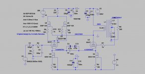
It's based on the original idea of Ross Mc Donalds depicted in Fig 9 acf-3, the last image here:
http://jrossmacdonald.com/jrm/wp-content/uploads/040CathodeFollower.pdf
My first version using a depleted pcb from another headphones amplifier which had the output transformers i use now in this project.The output transformers were made by Lazaroiu.
The subject was discussed and simulated also for the first time by G Sabac who helped me with the spice models here and also showed me some flaws in my design allthough i made it public after two days of intense listenings and i was very pleased with the sound:
Teardrop headphones amplifier - Accesorii audio - Forumul Electronistilor
If you need to see those discussions you need to register and translate .
The inductances are some aproximate values of the real transformer.The real values are a bit higher , but not by much.
Capacitors on the schematics have different values on the schematic as i use real bipolar nichicon muse bs and nichicon muse kz in paralel for cathode coupling.
An externally hosted image should be here but it was not working when we last tested it.
http://i68.tinypic.com/ea39ly.jpg
An externally hosted image should be here but it was not working when we last tested it.
http://i68.tinypic.com/2i1iohu.jpg
begining of pcb population:
An externally hosted image should be here but it was not working when we last tested it.
It's based on the original idea of Ross Mc Donalds depicted in Fig 9 acf-3, the last image here:
http://jrossmacdonald.com/jrm/wp-content/uploads/040CathodeFollower.pdf
My first version using a depleted pcb from another headphones amplifier which had the output transformers i use now in this project.The output transformers were made by Lazaroiu.
An externally hosted image should be here but it was not working when we last tested it.
An externally hosted image should be here but it was not working when we last tested it.
The subject was discussed and simulated also for the first time by G Sabac who helped me with the spice models here and also showed me some flaws in my design allthough i made it public after two days of intense listenings and i was very pleased with the sound:
Teardrop headphones amplifier - Accesorii audio - Forumul Electronistilor
If you need to see those discussions you need to register and translate .
The inductances are some aproximate values of the real transformer.The real values are a bit higher , but not by much.
Capacitors on the schematics have different values on the schematic as i use real bipolar nichicon muse bs and nichicon muse kz in paralel for cathode coupling.
Attachments
This can hardly be called a headphones amplifier, it's more like a tube effect...there's no special amplification due to it. I trust op-amps more when it comes to amplification. The harmonics content it's good, really pleasant , but the upper freq response is not so great as the OT has 1 primary and 1 secondary . In fact the OT was well figured initially, the original calculus made by Dan Minciu is quite good, it just needs the primary to be redestributed in 2 primaries, no more than that. Well some other guy took the merits and made bad replicas of the original OT design unfortunately...I'll remake the original OT design of Dan Minciu when i'll have the time! I just made some "mods" to the original completely different schematic that you know allready as the original green spider pcb in the photo is yours... and it was a "BAD...BAD" ideea as my design escaped the original miller compensation which killed completly the highs that were a small minority in the overall sound aniway, because now i can miss the highs, before that , i didn't know they were there...and you know...you can't miss something you never knew!
Nichicon Muse ES bipolar capacitors.According to these guy: Nichicon Muse ES bipolar caps measured: <-120dB THD, <-140dB IMD
up to 400 mv dc voltage over them, the Audio Precision couldn't measure any distortion due to them. C4-C12 on the schematic are actually one bipolar capacitor and i used two in parallel to make 2000uf.
up to 400 mv dc voltage over them, the Audio Precision couldn't measure any distortion due to them. C4-C12 on the schematic are actually one bipolar capacitor and i used two in parallel to make 2000uf.
Last edited:
- Status
- Not open for further replies.