Dibya,
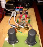
The Altoids tin we used is really very thin metal and a drill will tear it apart if you try to make the hole big enough for the vol pot shaft to stick thru.
I started the hole in the thin metal with a very small drill and used a piece of wood to act as a support when drilling. Then I used a reamer to enlarge slowy and carefully.
If you using a thicker metal aluminum case you should be able to start with a small drill then enlarge with larger drill bits until you get to the correct opening for the shaft size.
Its just with the really flimsy Altoids tin case that I used a reamer...
Alex
Note a Dremel tool with the proper bit will do the trick as well, just have to be careful.
Would someone kindly double check my math...
agdr Audio OPA1688 Parallel Super CMoy Specs
Output Current (peak): 150 mA per channel
Output Current (rms): 106.05 mA per channel
Output Impedance: ~0 ohms
Voltage Gain: 1x ("unity-gain amplifier")
Voltage Cut-Off Level: 8.4 Vnominal
Voltage Swing (peak): 7.4 Vdc
Voltage Swing (rms): 5.23 Vrms
Please Note: I am not using batteries but rather a RECOM RW-0509D DC-DC Converter which converts the 5V from a USB 2.0 DIY power-only cable to the required 9V. At max it is using under 1W (<180mA @ <5V).
Last edited:
*** BUMP *** Any electronic geniuses around to double check my math and nomenclature:
agdr Audio OPA1688 Parallel Super CMoy Specs
Output Current (peak): 150 mA per channel
Output Current (rms): 106.05 mA per channel
Output Impedance: ~0 ohms
Voltage Gain: 1x ("unity-gain amplifier")
Voltage Cut-Off Level: 8.4 Vnominal
Voltage Swing (peak): 7.4 Vp (aka Vdc)
Voltage Swing (rms): 5.23 Vrms
Please Note: I am not using two 9V batteries but rather a RECOM RW-0509D DC-DC Converter which converts the 5V from a USB 2.0 DIY power-only cable to the required 9V. At max I believe this converter is using under 1W (<167mA @ <5V).
__________________
agdr Audio OPA1688 Parallel Super CMoy Specs
Output Current (peak): 150 mA per channel
Output Current (rms): 106.05 mA per channel
Output Impedance: ~0 ohms
Voltage Gain: 1x ("unity-gain amplifier")
Voltage Cut-Off Level: 8.4 Vnominal
Voltage Swing (peak): 7.4 Vp (aka Vdc)
Voltage Swing (rms): 5.23 Vrms
Please Note: I am not using two 9V batteries but rather a RECOM RW-0509D DC-DC Converter which converts the 5V from a USB 2.0 DIY power-only cable to the required 9V. At max I believe this converter is using under 1W (<167mA @ <5V).
An externally hosted image should be here but it was not working when we last tested it.
__________________
Last edited:
Not sure what you mean by: "Voltage Cut-Off Level: 8.4 Vnominal"? Do you mean "maximum peak output voltage 8.4V"?
For the load on the DC-DC converter: the output is, as I understand it, 2 x 150mA @ 9V? That would be 2.7W load on the DC-DC which is probably 80% efficient so it would need an input of around 3.3W.
Jan
For the load on the DC-DC converter: the output is, as I understand it, 2 x 150mA @ 9V? That would be 2.7W load on the DC-DC which is probably 80% efficient so it would need an input of around 3.3W.
Jan
Not sure what you mean by: "Voltage Cut-Off Level: 8.4 Vnominal"? Do you mean "maximum peak output voltage 8.4V"?
For the load on the DC-DC converter: the output is, as I understand it, 2 x 150mA @ 9V? That would be 2.7W load on the DC-DC which is probably 80% efficient so it would need an input of around 3.3W.
Jan
The amp has a "safety cut off circuit" designed into it so if the power supply dips below 8.4V it turns off (to combat failing batteries on their last legs from damaging the board).
3.3W... how can that be? Maximum power from USB 2.0 is 2.5W (500 mA @ <5V). What am i missing here?
Hello folks, I’m very interested to make one of this amazing project, where can I get the boards from? Thanks
Leo
Index
Super CMOY Prices
I couldn’t see any link to order, there is a store in the menu of ale’s website but link is broken. I messaged Alex but no reply yet.
Any of you guys can recommend a good headphones amp to build so I take it with me when I traveling?
Tanks 👍🏼
Leo
I couldn’t see any link to order, there is a store in the menu of ale’s website but link is broken. I messaged Alex but no reply yet.
Any of you guys can recommend a good headphones amp to build so I take it with me when I traveling?
Tanks 👍🏼
Leo
You pay thru PayPal. To order and get his PayPal address you must contact agdrAudio first via his email here:
Contact
I want to power agdr board(single or paralel) with 12v single battery..
1-first choice using recom rw-1209d (12v to +-9v)
WoodyLuvr made this for usb power with recom rw-
0509d
2-second choice creating virtual gnd from 12v and obtaining +-6v. And choosing paralel board to obtain good amount of current.
I want to use second choice..
Is this meaningful to anybody?")
1-first choice using recom rw-1209d (12v to +-9v)
WoodyLuvr made this for usb power with recom rw-
0509d
2-second choice creating virtual gnd from 12v and obtaining +-6v. And choosing paralel board to obtain good amount of current.
I want to use second choice..
Is this meaningful to anybody?
Hi slmnklyc,
From what I can, tell your 1st choice would certainly work using the RW-1209D. Unfortunately, I can't find any distributors that have it in stock currently.
As for creating a virtual ground using a 12v battery for +/-6v, someone else might need to chime in on that. Without modification to the existing design, the board would never turn on as the voltage would be below the 7v power management cutoff point. You'd also have reduced headroom sound-wise.
Can you be more specific as to what type of 12v battery you're wanting to use and why? (throw away, rechargeable, etc...)
I'm powering the RW-0509D with 5v over USB like WoodLuvr and it's worked flawlessly since building it
Lavalier,
I am powering my small amp and dac with 12v car battery. I don't want to use AC. If I do that, I will have to buy good psu's for them. Generally good linear psu's are very expensive. I just want to complete my 12v System, that's it.
Maybe I will use the only buffer part of O2 design(also without battery management circuit) with 12v virtual gnd. I will use it with dac output only and probably I won't use any balanced armature headphone Types. So maybe it can be safe using O2 without battery management circuit..
I really like this cmoy design a lot except one thing. I wish there was an rca pcb input.. Of course it designed for portable use..
Do you know any sound comprasion between O2 and opa1688 cmoy?
Very pleased to report that my agdr Audio Super CMoy + WesionTEK Khadas Tone Board DAC headAMP build is still going strong now after 18 months (16 months since the DAC upgrade) operating "24/7, 365"... I simply leave "Steampunk" powered on all the time as both the amp and dac boards are designed to have extremely low idle currents in standby.
Full build can be viewed HERE.
Full build can be viewed HERE.
Last edited:
Same over here!
Though I think I built mine before yours, so it's been running even LONGER without a single issue. Hats off to AGDR on such a rock-solid design.
I keep planning to post photos of my build and if the stay-at-home situation continues long enough maybe I'll finally get around to it.
My single 1688 Super Cmoy is built in an aluminum enclosure and paired internally with a JDS Labs ODAC Rev B. I built mine for portable use, but I've wanted to build a second larger desktop version similar to yours with a decent quality stepped attenuator and likely pair it with that same Khadas board you're using.
slmnklyc Sorry I'm just now getting back to your message.
Hope everyone is staying healthy and safe out there.
Though I think I built mine before yours, so it's been running even LONGER without a single issue. Hats off to AGDR on such a rock-solid design.
I keep planning to post photos of my build and if the stay-at-home situation continues long enough maybe I'll finally get around to it.
My single 1688 Super Cmoy is built in an aluminum enclosure and paired internally with a JDS Labs ODAC Rev B. I built mine for portable use, but I've wanted to build a second larger desktop version similar to yours with a decent quality stepped attenuator and likely pair it with that same Khadas board you're using.
slmnklyc Sorry I'm just now getting back to your message.
I don't know of any off the top of my head and I don't personally own an O2 to compare it with but they're both built off very similar circuit design topologies with neutral/clean gain being the main goal. But sound comparisons aside, the muting relay to prevent pops/thumps and protect your headphones was one of the things that really sealed the deal for me.Do you know any sound comparison between O2 and opa1688 cmoy?
Hope everyone is staying healthy and safe out there.
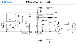
Hello, I apologize for the potentially dumb questions. I would like to add this headphone amp to one of my projects with a revised PCB. If I wanted to power a Super CMOY with a separate 15 VDC dual rail supply would I just omit all the power related items on the schematic?
Also if I remove the volume control do I need to change any of the component values elsewhere?
Thank you for your help.
Also if I remove the volume control do I need to change any of the component values elsewhere?
Thank you for your help.
Looks to me like a better solution than opa1622.
I had to use coupling cap but with opa1688 offset will not be necessary.
Im really happy used dip8 on this proto.
So will give it a try. The opa1688 would go in ic2 slot.
I had to use coupling cap but with opa1688 offset will not be necessary.
Im really happy used dip8 on this proto.
So will give it a try. The opa1688 would go in ic2 slot.
Attachments
Hello, I apologize for the potentially dumb questions. I would like to add this headphone amp to one of my projects with a revised PCB. If I wanted to power a Super CMOY with a separate 15 VDC dual rail supply would I just omit all the power related items on the schematic?
Also if I remove the volume control do I need to change any of the component values elsewhere?
Thank you for your help.
I've also been considering doing something similar and AGDR actually answered that exact question back on page 9
Good question! I'll bet there are other folks out there who AC-power their Super CMOYs.
The good news is that all you will have to do is run the +/-DC from your split power supply to the Super CMOY battery connection holes. Everything on the Super CMOY board stays the same. As long was your split supply is more than +/- 7.1Vdc (and less than +/-17Vdc) the low battery protection circuit will think you have fully charged batteries. If you use the alternate set of resistors in the BOM for lithium rechargeable cells it will drop that "low battery" point down to +/-6.26Vdc.
I've attached a picture of the Super CMOY battery wire holes below. What you would do is run the positive DC voltage from your split supply to the bottom terminal of the four, marked "POS", near IC3. Your negative DC voltage from your split supply would go to the "NEG" hole on the other end, near the board edge. Then the common ground wire from your supply would go to either one of the two center battery holes - doesn't matter which one - marked "POS" and "NEG". Be sure to twist all 3 of the wires from your split supply together to help eliminate noise pickup.
And that is it! The OPA1688, the TPS3701, and all the Super CMOY's parts are OK with up to +/-17Vdc power supplies. It would be up to +/-18Vdc, but the MC78L12 is only rated to 35Vdc. For more than the +/-11Vdc you get with two batteries you would have to check on chip power dissipation at very high volume levels with low loads (16R headphones). But for normal listening levels your should be just fine above +/-11Vdc.
The low battery cutoff circuitry is up by those battery input holes. The MC78l12 on the other end of the board is for the headphone relay circuit, which eliminates the turn-on and turn-off pops. Lots going on with that small PC board!
The batteries will provide 18V, just as you think. However IC5 is a voltage regulator that will bring that down to a stable 12V span (+/- 6V) which is then used by the rest of the circuit.
I guess the schematics would have been clearer if the regulator had been drawn as the output of the power stage instead of separate.
I guess the schematics would have been clearer if the regulator had been drawn as the output of the power stage instead of separate.
- Home
- Amplifiers
- Headphone Systems
- OPA1688 Super CMOY, 2x 9V with real ground and headphone relay - PCBs