the lower half is the 2Q CCS. It does not affect the bias voltage on the mosFET gate.
for a resistor loaded Follower I would suggest less than -12dB, maybe even a low as -20dB.
For CCS load Follower, -12dB should keep the harmonic at pretty low level.
for a resistor loaded Follower I would suggest less than -12dB, maybe even a low as -20dB.
For CCS load Follower, -12dB should keep the harmonic at pretty low level.
Last edited:
I've played with such a buffer a bit more. Looks like you want to keep away from the positive rail a fair bit (input capacitance nonlinearity seems to be the problem as things worsen at HF, so decreasing source impedance helps as well). Distortion into high-impedance loads tends to be minimum if steady-state output DC voltage is little more than needed for the respective output amplitude. So there's definitely a tradeoff between maximum level and distortion. In light of this you probably don't even want a DC-coupled output.
The distortion sims further up in this thread were taken with a circuit biased fairly high. This probably makes performance look worse than it would have to be. At ~10 mW into 400 ohms, 100 mA, 24 V supply, output biased at 4.83 V, and 1k source impedance feeding an IRF510 with ideal CCS, I'm getting -109 dB (2nd) / -120 dB (3rd). With a 15 V supply, it's a still-decent -92 dB (2nd) / -104 dB (3rd).
The distortion sims further up in this thread were taken with a circuit biased fairly high. This probably makes performance look worse than it would have to be. At ~10 mW into 400 ohms, 100 mA, 24 V supply, output biased at 4.83 V, and 1k source impedance feeding an IRF510 with ideal CCS, I'm getting -109 dB (2nd) / -120 dB (3rd). With a 15 V supply, it's a still-decent -92 dB (2nd) / -104 dB (3rd).
Last edited:
Current sink in source is only half job.. if you move current sensing resistor (R5) to FET's drain, replace Q1/Q2 with PNP (Q2 moved to up) - you'll get much more linearity cuz whole circuit will turn into current sink, like in mine amp 🙂 (this trick works with FETs too). Also like there additional current sink then will even more improve linearity:

Microcap says THD will be 0.00012% and its probably true (with BJT it really works fine in reality). Also in reality it can be necessary to add capacitive load decoupling filter on output (RL or simple R) to avoid oscillation.
And its possible to care about thermodynamic distortions and Early effect with ''double' follower, but this will take some 'fee' of voltage loss.
Attachments
Last edited:
.....................I don't think that factor-of-4 rule of thumb really applies to CCS-loaded followers. With the CCS the main source of voltage depence has been just about eliminated, and distortion into higher-impedance loads is much improved. ......................
.................At ~10 mW into 400 ohms, 100 mA, 24 V supply, output biased at 4.83 V, and 1k source impedance feeding an IRF510 with ideal CCS, I'm getting -109 dB (2nd) / -120 dB (3rd). With a 15 V supply, it's a still-decent -92 dB (2nd) / -104 dB (3rd).
Despite your alleging in post20 that the rule of thumb is flawed, your simulations in post22 supports my original contention.................for a resistor loaded Follower I would suggest less than -12dB, maybe even a low as -20dB.
For CCS load Follower, -12dB should keep the harmonic at pretty low level.
Keep the absolute maximum well above the normal audio maximum.
10mW into 400ohms is 2Vac
for the +-15Vdc sim version this is ~-14dB headroom. (2nd harmonic distortion has increased by 17dB rel +-24Vdc)
for the +-24Vdc sim version this is ~-18dB headroom.
I wonder what the +-12Vdc sim would show for the same 10mW into 400ohms?
But your rule of thumb alone won't help much, as bias setting tends to have a far greater influence than input level by itself. I'd say it's mainly important that you keep the input at least 3 V or so away from the positive supply and Vgs + ~1 V ~= maybe 5 V away from the negative supply at all times, so you could get a decent 7-8 Vpp on a +15V supply or 15-16 Vpp on +24V.
(RJM's sim used a +15 V supply while biasing the input at ~+12 V, and you can probably imagine what that means if you go in with a 2.83 Vp signal. Something like +8.5 V would have been much closer to optimum. That potentially is quite a change from a resistor-loaded follower.)
(RJM's sim used a +15 V supply while biasing the input at ~+12 V, and you can probably imagine what that means if you go in with a 2.83 Vp signal. Something like +8.5 V would have been much closer to optimum. That potentially is quite a change from a resistor-loaded follower.)
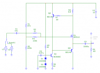
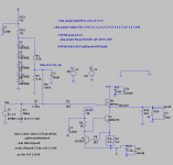
R11 & 12 look quite low. You don't need 10 to 12mA for a mosFET bias circuit.
The Blue LEDs would be better replaced with 4, or 5, Red LEDs. 1mA to 2mA would be enough for the Red LEDs allowing 1k, or more, to be used.
Any particular reason for using red. I prefer the blue color and less points of failure is better as any led failing will expose the headphones to significant dc.
You mean at the base of Q1? I did have a 100 ohms there but some people reported in some threads that at times that resistor causes instability and i took it out.You might need a base stopper or two to stabilise the 2q CCS
The low voltage LEDs have less noise.
They may also have lower dynamic impedance.
Generally a string of red LEDs is a better voltage reference than a Blue or White LED.
There may be a case for using IR LEDs and include one red as an indicator.
They may also have lower dynamic impedance.
Generally a string of red LEDs is a better voltage reference than a Blue or White LED.
There may be a case for using IR LEDs and include one red as an indicator.
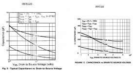
Hmm. Looks like MOSFET models vary greatly in accuracy. The stock IRF510 and IRFP240 models predict nonlinear capacitance related distortion that is an order of magnitude lower than the stock IRFZ120R model or Bob Cordell's IRFP240 model. Which results am I to believe? I suspect it's the latter ones that are correct...
Anyway, with a 10 kHz (!), 4 Vpp signal into 400 ohms and the IRFZ120R with a real CCS (2T similar to RJM, BC337-25 + 2N3055, 96 mA) at +15 V supply, I'm getting the following harmonics depending on input bias point:
7.4 V (min unclipped, the CCS likes >=~1 V = 6.8 R * 95 mA + Vce,sat): H2 -55 dB, H3 -72 dB
9.5 V: H2 -49 dB, H3 -64 dB
12.3 V (à la RJM): H2 -36 dB, H3 -45 dB
So clearly, the choice of bias point can make a difference of up to an order of magnitude here. (For comparison - for each 10 dB level decrease, H2 goes down by 10 dB and H3 by 20 dB. So getting H2 down an order of magnitude at same bias point requires reducing signal by an order of magnitude.)
Reducing source resistance from 1k to 10 ohms gives H2 of -73 dB to -90 dB instead, approaching the expected 40 dB reduction. So clearly, power MOSFETs want to be driven hard at higher frequencies. In practice we are often seeing gate stoppers of 100-220 ohms, which I guess is because speaker power amps are much more current limited than our little Class A follower and operate at much higher supplies to boot.
So let's test at +24 V instead:
7.4 V: H2 -69 dB, H3 -91 dB
12.3 V: H2 -63 dB, H3 -84 dB
16.3 V (output at +12 V): H2 -55 dB, H3 -73 dB
21 V: H2 -36 dB, H3 -48 dB
This thing is starting to look quite good even, but definitely prefers bias levels that put the output below midpolnt, ideally as far as the current source will permit at maximum signal amplitude.
So I chose the smallest p-channel MOSFET that the stock LTspice library would offer (BSS84) and put in a small buffer in front of the main FET with a 10k load resistor.
Bias +14.2 V (output at +12 V): H2 -72 dB, H3 -90 dB
17 dB less 2nd harmonic, not bad for a fairly minimal increase in complexity. A BC557C with a 10 pF Miller cap does about the same, maybe a dB worse.
So I put in an ideal CCS of 726 µA to replace the 10k (still with BC557C in), and...
Hey presto, H2 -82 dB, H3 -100 dB. We're seriously entering blameless territory.
(This time around, the BSS84 fares a bit worse, at -79 / -96 dB. Lower transconductance = higher output impedance in a follower.)
You could also go AC-coupled and use an npn / n-JFET / whatever.
Of course you could also use a boring old opamp follower (isolation resistor advised, capacitive load and all), but where'd be the fun in that? Besides, types with good capacitive load driving tend to use a bit more power than a little follower.
Back to +15V, same currents... best-case biasing for 4 Vpp (output DC at +3 V) gives H2 -83 dB, H3 -96 dB (down from -55 / -72 dB - THD wise that's going from about 0.2% to <0.01%). Clearly a 2-stage buffer is looking quite alluring.
Determining optimum "buffer buffer" current is left as an exercise to the reader. 😉
Last edited:
On to misterzu's circuit:
One of the things that I like about the plain MOSFET follower is its relative immunity to capacitive loading, and that may get lost here. But anyhow, let's simulate it:
I used IRFR120Z as before, BD140, 2N5551 and 1N4148 (Cordell). Same 10 kHz, 2Vp, 1 kOhm input and 400 ohm load as before.
Umm... sorry buddy, but that one sims with far from ppm-level distortion under these conditions. Somewhat worse than the plain CCS-loaded follower, in fact, as output towards the negative rail is a bit more restricted, and it looks like PSRR may suffer up top. (I assume it'll react more graciously to output loading though.)
+15 V supply:
7.4 V: H2 -54 dB, H3 -59 dB (onset of clipping)
8 V: H2 -51 dB, H3 -67 dB
9 V: H2 -48 dB, H3 -63 dB
12.3 V: H2 -31 dB, H3 -39 dB
Results at +12 V are expectedly worse. As I anticipated, the circuit is not at all happy when I add 10 nF of capacitive load - the threshold of oscillation is between 2n2 and 3n3. Rather marginal when headphone cables can have up to ~1 nF. By contrast, the plain buffer (even with pre-buffer) remains unimpressed even at 100 nF.
Attachments
Last edited:
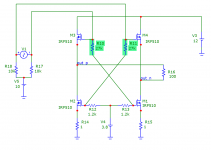
Compare with lower load resistance. On my pic it is 60 Ohm 😉
From my sim (and in reality for BJT) mine circuit produces 0.00012% THD on 1V on 60 Ohm load while has ~130mA total current consumption from 12V PSU. And CCS-loaded follower with same load/PSU numbers produces 0.06% of THD.
Sure for 400 Ohm load 100mA of quiescence current enough to compensate Vbe (or in case of FET - gate threshold) variations caused by drain current deviation that is 2/400 = 5mA of 100mA and my circuit doesn' have much benefits due to more active elements involved.. But lowering load resistance to 60 Ohms things will change: 33mA deviation of 100mA quiescence causes huge gate threshold variation and - distortions. Mine current-around-feedback essentially stabilizes drain current so it has its benefits when load currents comparable to quiescence current. There however some other side-benefits too: limited short circuit current and constant current eaten from PSU, that effectively excludes PSU from signal path (so PSRR will improve actually).
About capacitive load - yes, as I wrote output filter is recommended. For example 2Ohm resistor or 1uH + 33 Ohm in parallel will completely fix that problem. However on practice simple follower that has high enough input impedance also sometimes tends to oscillate, sure less then mine circuit but still can require additional frequency compensation or output filter. I saw oscillation of stupid Darlington pair loaded with single resistor (and be sure that power decoupling was OK). Not sure about reasons, but have few ideas about this: at first, follower itself has inductive kind of output resistance on high frequency (see http://www.radioeng.cz/fulltexts/1997/97_01_05.pdf for example) that together with capacitive load forms oscillatory circuit. Another idea is stray EMI feedback between output and input that can cause enough level amplification together with phase delay.. So this problem is not belonging exclusively to mine circuit 😉
Last edited:
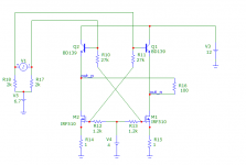
Also wanna share another schema completely different but based on same idea of keeping collector current stable. This another idea is true zero feedback and having very low THD on low collector current, BUT to be low-THD it must be fine tuned to load resistance cuz unlike circuit in my prev message it doesn't have current stabilizing feedback (so when simulated in different simulator it can require different resistors values). Another problem (or benefit 🙂 ) - its bridge circuit and requires balanced signal. Attached simplified circuit, it misses some not-critical points (like auxiliary voltage source) to be more easy for understanding..
PS sorry for double message, can't edit previous one since it posted more than half of hour ago..
PS sorry for double message, can't edit previous one since it posted more than half of hour ago..
Attachments
Last edited:
I suspect your IRF510 model is as optimistic as the one that comes with LTspice. Or maybe it's the library file found on the web where it's modeled as a subcircuit - that one explicitly says it does not model nonlinear capacitance. I also used a different type of current source transistor with less beta (but higher Va).
Just did a little comparison at 300 mVrms (Vsource 450 mVp) into 32 ohms at near-optimum biasing (output at 3.07 V for buffered follower, 3.66 V for misterzu):
10 kHz: both buffered follower and misterzu around H2 -60 dB, H3 -90 dB
1 kHz: buffered follower does not improve over 10k, but misterzu improves by 20 dB, giving H2 -84 dB, H3 -114 dB.
And same at 60 ohms:
1 kHz, 60 ohms: misterzu unchanged over 32 ohms (-84 / -114 dB), buffered follower improves to H2 -71 dB, H3 -106 dB.
10 kHz, 60 ohms: misterzu almost unchanged over 32 ohms (-65 / -96 dB), buffered follower same as 1 kHz.
(The unbuffered follower is only marginally worse than the buffered version here, so we're current-limited.)
Clearly the circuit does work, and its loop gain follows a first-order slope in the 1-10 kHz range - so it is, in fact, a feedback affair as the schematic would already suggest. It is of most use for low-impedance loads and at low frequencies.
Going by the old rule "if you can't make distortion negligible, at least make it constant over frequency", I would probably prefer the standard or buffered follower for at least medium-impedance loads of 60-100 ohms up, depending on headphone sensitivity. The buffered follower shines when driving higher amplitudes into high-impedance loads. And I suspect a little MAX97220 performs as well as any of them at a fraction of idle power draw, though obviously that's not exactly a fair comparison...
I'm using Microcap 9.0.6.1 with its default models, so not sure here whose model is more correct 🙂
And yes - there is feedback in my circuit, but actually its same feedback as in follower loaded with CCS made on 2 transistors, but only in my circuit this feedback works more 'actively'. In CCS-loaded follower feedback stabilizes current flowing through CCS while in mine sch. - follower essentially 'put inside of CCS', becoming part of that feedback loop.. I don't deny that 🙂
And yes - there is feedback in my circuit, but actually its same feedback as in follower loaded with CCS made on 2 transistors, but only in my circuit this feedback works more 'actively'. In CCS-loaded follower feedback stabilizes current flowing through CCS while in mine sch. - follower essentially 'put inside of CCS', becoming part of that feedback loop.. I don't deny that 🙂
Last edited:
sorry for double message again, but just noted that you're using IRFR120 in your model instead of IRF510 in my. According to datasheet IRFR120 has more than twice bigger input/output capacitance than IRF510 and not surprising that it works worse in current feedback loop on high frequencies. I tried to use IRF120 (that looks very similar to IRFR120) in Microcap in my sch. and got VERY bad results, even worse than you got.
Attachments
Last edited:
Even then, I'd expect 6 or 8 dB more distortion, or having to halve source impedance... not a whole order of magnitude of difference. There must be more going on.
Anyway, your current servo (which is what your "everything in a current source" circuit is) actually does a splendid job. At zero source impedance, 10 kHz distortion at 300 mVrms into 32 ohms becomes H2 -108 dB, H3 -134 dB. And that's after I gave the upper BD140 3 nF of Miller capacitance to make the whole shebang stable into 400R || 100 nF (results with 1 nF are almost identical though). At 100 pF, you would need a gate stopper resistor, but 10 ohms will do.
Raising supply to +30 V with 10 V input bias, I'm getting H2 -120 dB, H3 -148 dB. With 400 ohms, it's H2 -127 dB. For comparison the plain follower with CCS:
400 ohms: H2 -105 dB
32 ohms: H2 -62 dB, H3 -92 dB
Quite a remarkable difference!
Next I'll be trying the combination with a bootstrapped cascode. Constant current and constant voltage, that MOSFET will turn out totally spoiled... 😉
I checked about the LED noise in this link. It seems the blue ones are the noisiest and red are pretty much are the best. IR like to run at near maximum current capacity for least noise. So changing to 5 red LEDs.
Changed the voltage back to 15v, power dissipation becomes high after that. Iq is about 250ma. LED current is 2.5ma and small transistor is at about 5ma. Once i have identified the chassis and heatsink etc, I might experiment with higher voltages and/or higher Iq.
Currently both the mosfet and transistors are running at about 3.6W avg power, sending about 100mw to the load. I plan to mount both channels on a single heatsink. So total about 15w avg power and say about 10W music power. Worst case Ambient temperature about 40C, Max HS temperature - about 60, so ballpark about 2C/W HS should be ok for this.
If I do decide to use a pot at the front, is 100k a good value for this.
Attachments
2sgrossklass I initially designed and tested in HW this circuit for BJT but occasionally put IRF510 in sim instead of BJT and found that it simed good too. But didn't test it with FET in HW yet, but going to do this soon (on breadboard). So may be for MOSFET its not worth using and good sim results caused only by bad FET model, I will let you know when get real-world results.
Last edited:
Simulated results with current servo plus bootstrapped cascode look excellent so far, I'm getting -114 dB H2 for 10 kHz at 2 Vp into 60 ohms (up to -97 dB with very slow decay into 20 ohms, still very low absolutely speaking) and ppm-level distortion into lighter loads or at the lower end of the bias range - all this with a 1 kOhm source impedance! Distortion remains very low until the onset of clipping, both voltage and current wise.
Usable input range on +30 V supply (which I am using for now) is about +8.2 V to +27 V, so about 19 Vpp max. I could still go from 4 red LEDs in the cascode back to 3 though, which would buy another 1.8 V or so.
Operation down to +15 V looks feasible. In fact, I just tried this with all 4 LEDs in and still obtained a very good -118 / -131 dB into 60 ohms. (With little headroom over 2 Vp, of course. A little bias shift will get me 2.83 Vp at -114 / -122 dB though, and upping source resistance to 2.5k gives a still-good -110 / -117 dB.)
The bootstrapped cascode still is a bit rough around the edges now and waiting to be optimized, but things are looking very promising indeed. +PSRR looks to be about 100 dB at 100 Hz, over 80 dB at 1 kHz and over 60 dB at 10 kHz, which is certainly decent (opamp follower level at 10 MHz and change of GBW). Some tweaking may still be useful to maintain ppm-level distortion in real life. Then again, with MOSFET current kept nearly constant, the circuit generates very little rail pollution by itself. Ground is a different story, at least until you recombine current source + load return currents. In split supply operation, the negative rail would have to provide load current.
Attachments
Last edited:
wow this looking quite a mad...
BTW I breadboarded initial circuit (no cascode)..
My PSU gives 18.5V (I don't have linear 15V PSU). I tested 1.5Vpk on 68Ohm load. Gate offset was approx. 10.2V. And 1k resistor in signal source path.
So brief numbers: 0.0015% at 1kHz and 0.006% at 10kHz (mostly 2nd and 2rd harmonics, and this numers are decreased by sound card's own THD that is 0.0008% and 0.005% respectively), so you were right about IRF510's model and FETs are not very good for this kind of circuit, at least without your cascode mod.. And it will be interesting to check with cascode, but I just need to find 12Volts more 🙂
Last edited:
- Home
- Amplifiers
- Headphone Systems
- class A Buffer