While these numbers are not ppm-level, they are a lot better than what the IRFR120Z model predicts. In fact, the LTspice IRF510 model predicts 0.001% (1 kHz) / 0.007% (10 kHz) for 1.5 Vp (3 Vpp) input with the supply and bias levels given, not a million miles from your practical results. So maybe that's not so bad after all?
Simulation says that the circuit with bootstrapped cascode should work fine on +15 V, so I'd claim the same for +18.5 V. (Claimed distortion would be H2 -111 dB / H3 -117 dB, 4.5 Vp into 60 ohms then, bias +10.5 V.) You don't have to use a LED string, the voltage seems close enough to a standard 5.6-6.2 V zener, I'm just not sure about noise implications. If you don't need to cover the entire voltage input range, you can also get away with just a bias resistor. PSRR is not likely to get any better, obviously, but distortion seems essentially unchanged.
Results with IRF510 + bootstrapped cascode aren't an awful lot different over the IRFR120Z model, but -118 dB / -130 dB at 10 kHz sounds quite good as-is. H2 is a bit higher at 1 kHz, interestingly, but -116 dB still is nothing to sneeze at. Maybe there was some cancellation going on before. (2Vp/1k/60R.) 10k distortion is barely up to -113 dB H2 at 25 kOhms of source impedance - so you could even use a 100k volume pot here. The bootstrapped cascode really helps there.
How interesting. I put in a BD139 for the MOSFET, and results are fairly similar in the circuit w/o bootstrapped cascode, but the improvement from the cascode is much smaller, only about 20 dB at 10 kHz. By 1 kHz, however, distortion is back in check. I would assume that BJT base current is at fault here, which reflects the not-perfectly-stable device current back to the input (beta only is about 100 after all), so higher current servo gain at 1 kHz helps. The MOSFET, being the voltage-driven device that it is, does not have this sort of distortion mechanism.
Next step - can we do this in push-pull, too?
Next step - can we do this in push-pull, too?
2 sgrossklass > when used BJT the circuit behaves as CCS for singal source. Small current (100mA/hfe) but constant. So in this case source must be something that likes such kind of load (like that circuit I used in headamp or opamp). If source has linear resistance then better add one more follower on BC548C - that will increase input impedance and thus improve linearity when working from resistive high-impedance source.
Hmm. An extra follower does improve Ic stability - but distortion remains unchanged nonetheless, and the same amount is present on the input side. It does get a bit better if I shift bias down, but that's in the un-cascoded follower.
So it seems the cascode reduces current servo loop gain in the bipolar follower, I'll have to think about why that is. Anyway, I could still back up on compensation capacitance. Still, no dice. Vbe and Ic are super-constant, yet distortion has not improved one bit.
Oh, Ib is definitely non-constant. Neither is Ie (same variation appears there, so apparently the servo takes over the function over providing current gain above 1).
Looks like we're servoing the wrong thing - Ic rather than Ie. In the MOSFET it didn't matter because once you take care of the capacitive effects, it essentially doesn't have any gate current to speak of! (And the bit of gate leakage would not even be a direct function of the signal for the most part.)
Sticking with MOSFETs for now, it seems the circuit likes types with high gm (IRF530 gives lower distortion than IRF510). Kinda expected for a follower though, I guess. The current servo with follower also brings down 1 kHz distortion at 2 Vp into 400 ohms to about -130 dB H2, or -117 dB at 4.5 Vp into 60 ohms (with '510). Low enough, I say.

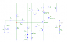
BTW why did you use BJT in FET cascode? I tried to put same IRF510 there and got much better results. Also I played a bit with compensation caps to make simed pulse response stable. Also I found another IRF510 model in MC that seems gives more precise results, so.. schematic attached.
BTW about zener instead of LEDs. I think its noise will not be an issue here cuz its attached to output that has much lower impedance so that noisy fluctuations of zener's minor current flowing via 33K resistor will be neglible.
PS What I really like in such cascode schematic - that it keeps thermal state of driver transistor stable, effectively cancelling 'memory' distortions. Not sure if they're noticable or just an audio-myth, but its good to have another checkbox marked🙂
Attachments
Last edited:
I hadn't tried that because I thought voltage drop (and resulting loss of headroom) would be too high anyway.BTW why did you use BJT in FET cascode? I tried to put same IRF510 there and got much better results.
I see you changed your compensation, that may also play in here.
I'm getting rather worse results for now. Not surprisingly though, since drain is now over a volt below gate, and feedback capacitance must be tremendous. Let's fix that...
Huh. The higher a zener voltage I choose for the cascode, the higher my distortion gets. And if I choose it low the circuit will eventually tend to break into oscillation around 10 MHz (must be quite local). Same if I increase supply. Mmkay, making the servo loop a bit slower fixes that. Still, distortion remains rather worse than before, and it's a current-related thing.
If in doubt I would say that having two MOSFETs in a cascode isn't doing our follower gm any good. I also suspect funny things may start happening in our cascode if the two MOSFETs get very close in their properties (double pole).
Oops, yesterday's values were at 1 kHz, now I had 10 kHz again. I was wondering why I couldn't reproduce them. Still, 10 kHz at 4.5 Vp into 60 ohms at -107 dB H2 / -119 dB H3 doesn't seem so bad. The MOSFET cascode actually performs pretty much the same, -106 dB H2 with a 4.7V zener (I suppose the bootstrapping may be a hint less effective, I saw input H2 at -120-ish dB). (+10 V bias, +18.5 V supply.)
Maybe I should remove the extra follower first. With this high-frequency stuff, less can be more...
Yep, that works. Not much change in distortion though, +10.5 V bias gives -106.5 dB H2, -123 dB H3. And capacitive load driving is not good at all, not even 10 nF is stable.
Last edited:
Capacitive load can be easily decoupled with 1u inductance + 30 Ohm or simple serial 3 Ohm.
About THD - when getting different numbers in different sims or with different models - only hardware will estimate it more or less exactly. Probably on weekend I will try to play with cascodes.
About THD - when getting different numbers in different sims or with different models - only hardware will estimate it more or less exactly. Probably on weekend I will try to play with cascodes.
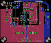

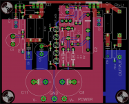
Have you connected P1+C4 to the incoming Signal Return/Ground? I think any signal at this bottom connection MUST be ultra clean since the top end is connected direct to the input at R7 and bypasses the input RF filtering, (which you have not fitted).
Looking at the red top plane on the PCB you seem to have this connected correctly.
But the OUTPUT R11 and OUTPUT Return are connected to the Blue plane. This is the dirty Power Plane.
You have a trace connection between the signal Return/Ground and the Power Plane. I recommend you change this to a resistor//diodes to help attenuate ground loop currents when you connect the pre into a system. Read D.Joffe
It seems to be Pass philosophy to use R7+Q2 capacitance as the input filter. I don't agree with this wide open style of input. Fit a real RF filter at the input.
To extend the pre-amp LF response I would change R6 to ~220k to 330k and then let the power amp shape the final LF roll-off.
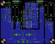
Last edited:
Should I also add a zobel (10R + 100nf) and thiele networks (1uH and 10R) at the output. There wasnt any issue in sims with 10nf capacitive load also.
The Thiele Network is a combination of R+C and L between the output and the load.
The L||R is a damped inductor. It alone is NOT the Thiele Network.
Read Dr Cherry's article discussing the various ways of using the Thiele Network.
The L||R is a damped inductor. It alone is NOT the Thiele Network.
Read Dr Cherry's article discussing the various ways of using the Thiele Network.
One of the best ways of isolating capacitive loading from the feedback is to use a resistor attached to the output pin.Should I also add a zobel (10R + 100nf) and thiele networks (1uH and 10R) at the output. There wasnt any issue in sims with 10nf capacitive load also.
Power amplifiers rarely use this because the full output current of many amperes has to pass through this isolating resistor. But some do and values around 0r1 to 0r22 are not uncommon.
Pre-amps/Buffers that feed tiny output currents into quite high substantially resistive loads can tolerate a resistor on the output with virtually no loss of performance. Try values of 10r to 100r and see what you measure/hear.
The B1 uses 220r, the DCB1 uses 100r
Many balanced impedance outputs use ~50r
Power amplifiers often use R||L (so there'is no problems with amperes) also together with R+C
However from my experience amplifiers rather indifferent to indictuve load and thus R+C doesn't change anything measurable as I saw. But with capacitive load things completely different and R||L can be very useful even when used alone..
However from my experience amplifiers rather indifferent to indictuve load and thus R+C doesn't change anything measurable as I saw. But with capacitive load things completely different and R||L can be very useful even when used alone..
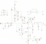
Fixed the output ground, added the rf filter and the output networks, diodes to the input. Can the output resistor and R||L at the output coexist.
Will test out the LF response while breadboarding.
Couldn't find Dr cherry's article, do you have a link for that.
Will test out the LF response while breadboarding.
Couldn't find Dr cherry's article, do you have a link for that.
Attachments
any suggestions on a power supply for this. I was thinking maybe crcrc followed by a cap multiplier?
Yes you can use a Zobel and an output inductor.
Yes you can use an output resistor and an output inductor.
The output resistor gives a resistive element to any reactive load that is presented. This added resistance, mounted very close to the output pin of the mosFET, is a very effective method of stabilising an active stage.
Yes you can use an output resistor and an output inductor.
The output resistor gives a resistive element to any reactive load that is presented. This added resistance, mounted very close to the output pin of the mosFET, is a very effective method of stabilising an active stage.
There is a base stopper on one base lead of the 2Q CCS.
Is this the correct base that can benefit from the added stopper resistance?
I don't know, I am asking !!!
Is this the correct base that can benefit from the added stopper resistance?
I don't know, I am asking !!!
Should work, maybe a bit overkill even (basic circuit PSRR ought to be workable as-is).any suggestions on a power supply for this. I was thinking maybe crcrc followed by a cap multiplier?
Please note that a cap multiplier is an inherently small-signal circuit. Input voltage Vin must never drop below Vout + Vce,sat(Ic) or you're screwed. Since steady-state Vout = Vin - Vbe(Ic), the maximum allowable peak ripple voltage works out to
Vripple,p = Vbe(Ic) - Vce,sat(Ic) at desired Ic.
This application thus favors parts with low saturation voltage that aren't oversized too much. Maybe BC337/327 or similar. Then you can hope for >0.6 V allowable input peak ripple. (Unfortunately this kind of transistor tends to have lowish Early voltage, so actual ripple rejection may not set any new records. Win some, lose some.)
The same caveats re: capacitive loading as for any emitter output apply.
- Home
- Amplifiers
- Headphone Systems
- class A Buffer