Hello,
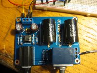
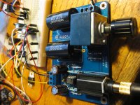
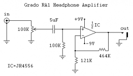
I just made one for my 80i/MS1's. Here are the diagrams i used, i first made one on a prototype board before i found kits for sale on ebay. Have a search for RA1 kits as i won an auction for £6 which was a complete bargain as the board is very nicely made. I didn't use any of resistors/caps/vol pot supplied as i had better quality items to hand, but it was worth every penny just for the PCB. Well worth building one as it sounds very nice
Have fun...
Attachments
I just ordered a kit from Along 1986
DIY RA1 Headphone Amplifier Kit Power Amp JRC4556AD C39 | eBay
DIY RA1 Headphone Amplifier Kit Power Amp JRC4556AD C39 | eBay
Hmm. I always thought the RA-1 were using an inverting topology. (But no, seems it's not.) Otherwise you wouldn't need these high resistor values for the feedback network which are needlessly increasing noise and distortion here.
The 4556 ain't a low-noise king but it is better than a 10k resistor in terms of voltage noise, and it would not be bothered at all by driving feedback resistors downsized to 1k2 + 4k7. Not to mention that an impedance imbalance of 80-100 kOhms (+ input: 0-20k, - input: ~100k) is inviting input impedance distortion.
A 10k-20k volume pot would also be preferred for noise reasons. Sources that cannot drive 10k with authority seem to be about as common as hen's teeth nowadays.
If you feel like going inverting for minimum distortion, you might try a 20k pot and 22k and 100k resistors, or a 50k with 47k and 220k, or a 10k with 10k and 47k (assuming your source is not bothered by 5 kOhms of load when the amp is cranked all the way up).
Basically, swap the 121k and 464k resistors for 1.2k and 4.7k jobs (regular 1% MF will do; you can go for 1.21k and 4.64k 0.1% if you really want, but that sort of precision is entirely unnecessary), and swap the 100k pot for something closer to 10k. Et voilà, a circuit that does exactly the same as before, except with less hiss and distortion. That's about as close to a free lunch as it gets.
I don't have good enough data on the 4556 to determine the improvement in distortion (going by the rather low input bias current for a bipolar, I'm guessing it may be less susceptible to input impedance distortion than other common opamps), but noise should go down by about 12 dB.
Unmodified noise levels are expected to be at about 27 µVrms across the audio bandwidth or -91 dBV, and would be audible on sensitive headphones and in-ears from about 120 dB SPL / 1 V up (even my old AKG K26Ps as small on-ear cans were rated 125 dB/V, though values that high are mostly reached by BA in-ears which can hit 130-135 dB/V).
Using the 4556 in inverting configuration may be most interesting when using it as a buffer and driving relatively high-impedance headphones, conditions that keep output stage distortion at bay while maximizing common-mode distortion in the non-inverting circuit (which is neatly eliminated when going inverting).
Think i'm getting my head around this, the concept that resistors create noise is new to me, never knew that.
Found this handy site i've been playing with Electronics Calculators and got the following numbers,
stock
121k/464k = 4.83 gain w/ 72.54 µV, -83 dB relative to 1 Vrms noise
modded
1.2k/4.6k = 4.83 gain w/ 28.5 µV, -91 dB relative to 1 Vrms noise
Question is how does the value of the pot tie into this, for example if i change to 1.2k/4.6k and leave the 100k pot what happens?
Thanks again for the help
I'm afraid that noise calculator doesn't work properly. For example, when using R4 = 1k and a noiseless opamp, there should be precious little difference between R3 = 100k, 1meg or 10meg, since the inverting input sees R3 and R4 in parallel (which is ~=R4) and voltage gain is 1+(R4/R3) ~= 1 in all of these cases. Yet the results returned are markedly different.
I've had a look at the code now. He's calculating voltage noise for all the resistors and the pot individually, applies gain and then RMS sums it all up. That's totally wrong. If you ever get anything resembling a correct result out of it, well, even a broken clock is right twice a day...
I've had a look at the code now. He's calculating voltage noise for all the resistors and the pot individually, applies gain and then RMS sums it all up. That's totally wrong. If you ever get anything resembling a correct result out of it, well, even a broken clock is right twice a day...
Look at the impedance that the noninverting input sees. It is (pot wiper to ground resistance) in parallel to (top to pot wiper resistance + source output impedance). Worst case, wiper at half pot + source (-6 dB setting), where it becomes 1/4 of the whole shebang. So the noninverting input may see up to 25 kOhms with a 100k pot when driven from a low-impedance source. Kinda high if the opamp contributes as much voltage noise as a 5 kOhm resistor or so.Question is how does the value of the pot tie into this, for example if i change to 1.2k/4.6k and leave the 100k pot what happens?
PS: Here's an online opamp noise calculator that actually works, brought to you by my shoddy JS coding skills and the Web 1.0. (Look Ma, I found Math.round()!  ) It's still a bit unfinished right now, but it does already work for calculating minimum noise level, and correctly as far as I can tell...
Resistors as dissipative elements have a certain amount of available thermal noise power all the time (a fundamental thermodynamics thing). Their resistance determines how much voltage noise (when unloaded) or current noise (when short-circuited) you get as a result.
Apart from a "noise" perspective, a "signal" perspective can be equally handy. You can say that using a lower-value volume pot, for example, decreases voltage noise. But at the same time, you can also argue that noise power has remained constant while signal power has increased (as the lower-value pot is drawing more current from the source). Both descriptions are equivalent, but the latter is better suited for understanding why lower resistor values tend to reduce noise (at least when working in the voltage domain, as often the case in audio).
) It's still a bit unfinished right now, but it does already work for calculating minimum noise level, and correctly as far as I can tell...Resistors as dissipative elements have a certain amount of available thermal noise power all the time (a fundamental thermodynamics thing). Their resistance determines how much voltage noise (when unloaded) or current noise (when short-circuited) you get as a result.
Apart from a "noise" perspective, a "signal" perspective can be equally handy. You can say that using a lower-value volume pot, for example, decreases voltage noise. But at the same time, you can also argue that noise power has remained constant while signal power has increased (as the lower-value pot is drawing more current from the source). Both descriptions are equivalent, but the latter is better suited for understanding why lower resistor values tend to reduce noise (at least when working in the voltage domain, as often the case in audio).
Nice work on the calculator, i need to order a few elecy bits so i'll get a few 1.2k and 4.6k resistors to experiment with. Does the size of the resistors make any difference to noise, e.g 1/4w, 1/8w etc?
Also whats your preference on decoupling caps around IC's/Opamps, do you favor mlcc ceramics or metal film?
I recently picked up an old analog scope so will be interesting to see if i can measure/quantify any difference. ...well interesting to me anyway
Thanks again..
Also whats your preference on decoupling caps around IC's/Opamps, do you favor mlcc ceramics or metal film?
I recently picked up an old analog scope so will be interesting to see if i can measure/quantify any difference. ...well interesting to me anyway
Thanks again..
Max Pdiss by itself generally doesn't, but resistor type very well may. In SMD, thin-film is quite equivalent to leaded metal film. Thick-film is more like carbon film or carbon comp (I forgot which), not that great in both linearity and excess noise.Nice work on the calculator, i need to order a few elecy bits so i'll get a few 1.2k and 4.6k resistors to experiment with. Does the size of the resistors make any difference to noise, e.g 1/4w, 1/8w etc?
Audio stuff usually is noncritical enough that either films or ceramic X7R will work fine (or 'lytics, actually...). I suppose surface-mount ceramics are good for higher frequencies if need be - as a rule of thumb, the smaller the better there.Also whats your preference on decoupling caps around IC's/Opamps, do you favor mlcc ceramics or metal film?
Here is a link for JRC4556 based CMOY component values
NwAvGuy: Cmoy With Gain
R1=1.3K
R2=360
Gain = 1+ (1300/360) = 4.6X = 13.2 dB
NwAvGuy: Cmoy With Gain
R1=1.3K
R2=360
Gain = 1+ (1300/360) = 4.6X = 13.2 dB
Great link thanks Avail.
I'm still waiting for some resistors to arrive to experiment but that thread inspired me to have another play with this project. I measured 2.5mv and 2.1mv DC offset which seems really good so i plugged my 80i's into it for some more testing. I quickly discovered it has way too much gain for these cans. With an ODAC as a source playing a 0db 1khz test file i measured 2.3volts at the amp input, output from the amp was 9.85v on full volume which seems a little excessive. I figure its got around 4.8x gain at the moment but i am unsure as to what setting is the best to use with Grado cans, or other 32ohm loads?
On my Objective2 i settled for zero gain, or unity for use with my two Grados, and 2.5x for the HD650's but it has two stages of opamps so i'm unsure if that's the overall gain ratio, or just the output stage? Basically should i configure the RA-1 for 1x gain, or 2x?
Cheers,
Mark
On my Objective2 i settled for zero gain, or unity for use with my two Grados, and 2.5x for the HD650's but it has two stages of opamps so i'm unsure if that's the overall gain ratio, or just the output stage?
That is the overall voltage gain on the O2 since the second stage is set up as a unity gain (voltage gain = 1) current buffer. Only the first stage provides voltage gain.
As guidance on how much gain you need, this table here may be helpful. The ODAC basically delivers CD player output level, so you can apply the results as-is. Grados are listed with -7 dB, so unity gain is plenty.
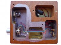
I just completed building the kit from Along. The switch that came with the kit didn't work so I have it hooked up to the battery clip directly. When I power it up it will play for about 20sec. then start distorting and cut out. If I disconnect the battery and connect it again it will do the same thing.
I have a feeling it may be a problem with the crappy pot that came with the kit. Can I just pull it off the board and run it without a pot?
I have a feeling it may be a problem with the crappy pot that came with the kit. Can I just pull it off the board and run it without a pot?
If I disconnect the battery
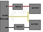
It is probably just a typo, but you are referring to one singular battery. You are using both battery clips and two 9V batteries at the same time, right?
You really do need to use a switch with this because both batteries need to be connected and disconnected at essentially the same instant. If you are just disconnecting one battery but not the other you will put a DC voltage on your output (and headphones). Having only one power rail "on" but not the other has also been known to kill NJM4556A chips in the O2 amplifier.
Suggestion: have the seller send you a replacement switch and another NJM4556A chip.
Last edited:
Thanks ADGR
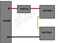
There is something I'm not understanding about wiring the switch and 2 batteries This is how I have it now but I don't think the switch connection is right. This switch has 6 terminals which makes me wonder if one side should be for one battery and the other side of the switch for the other battery.
There is something I'm not understanding about wiring the switch and 2 batteries
This is how I have it now but I don't think the switch connection is right. This switch has 6 terminals which makes me wonder if one side should be for one battery and the other side of the switch for the other battery.Attachments
- Home
- Amplifiers
- Headphone Systems
- grado ra1 clone