Sorry, no update other than I have the BOM for the front end board and the revised FE board with the error corrected. Just need to wrap up the more pressing (paid) work before I do more hobby work. Nice thing is that Vunce will be doing the build of th Aurum-X with me is parallel - we just need to start!
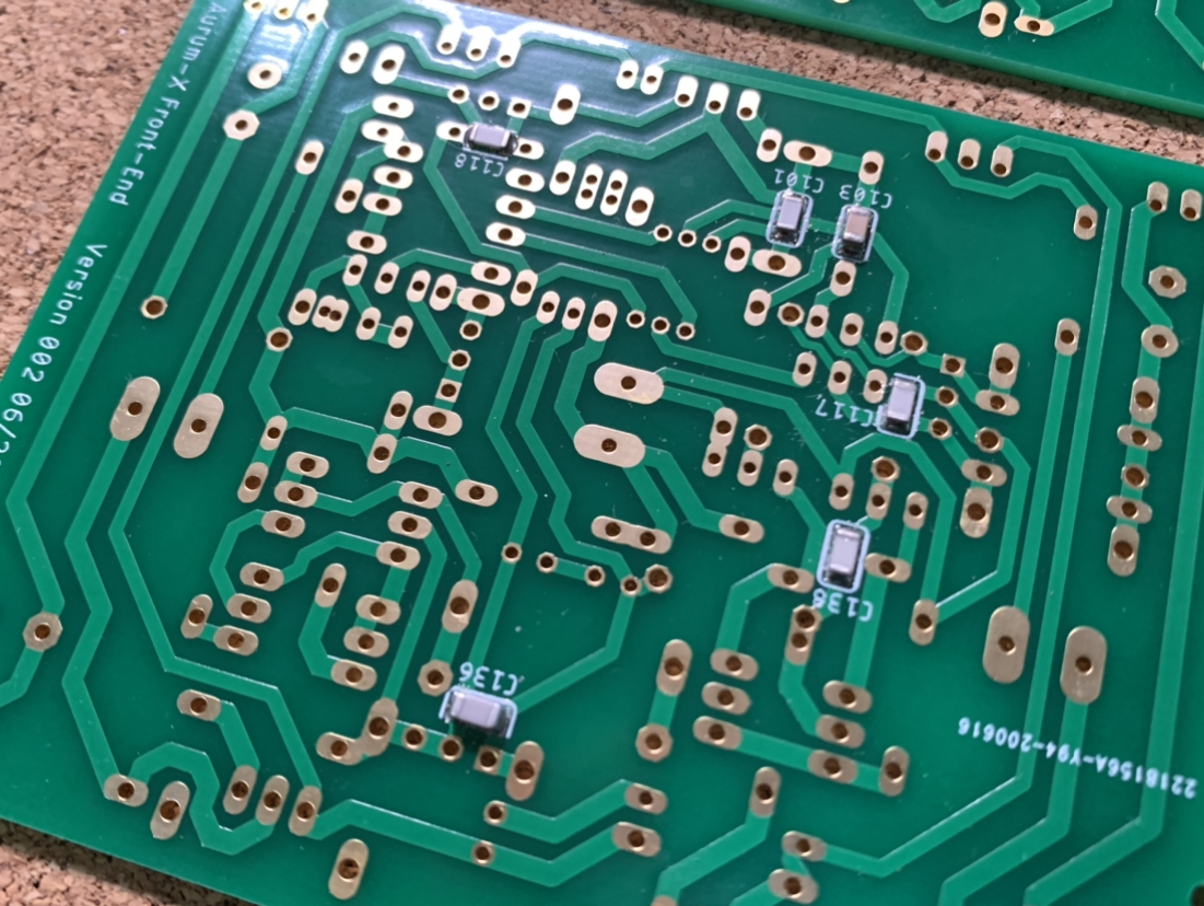
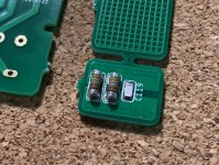
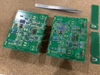
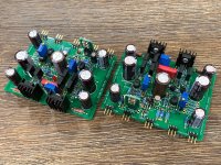
Finally starting to build the Aurum-X front end. SMT caps installed and resistors and diodes stuffed.
Will solder tomorrow. Then install actives and larger caps.
Will solder tomorrow. Then install actives and larger caps.
Attachments
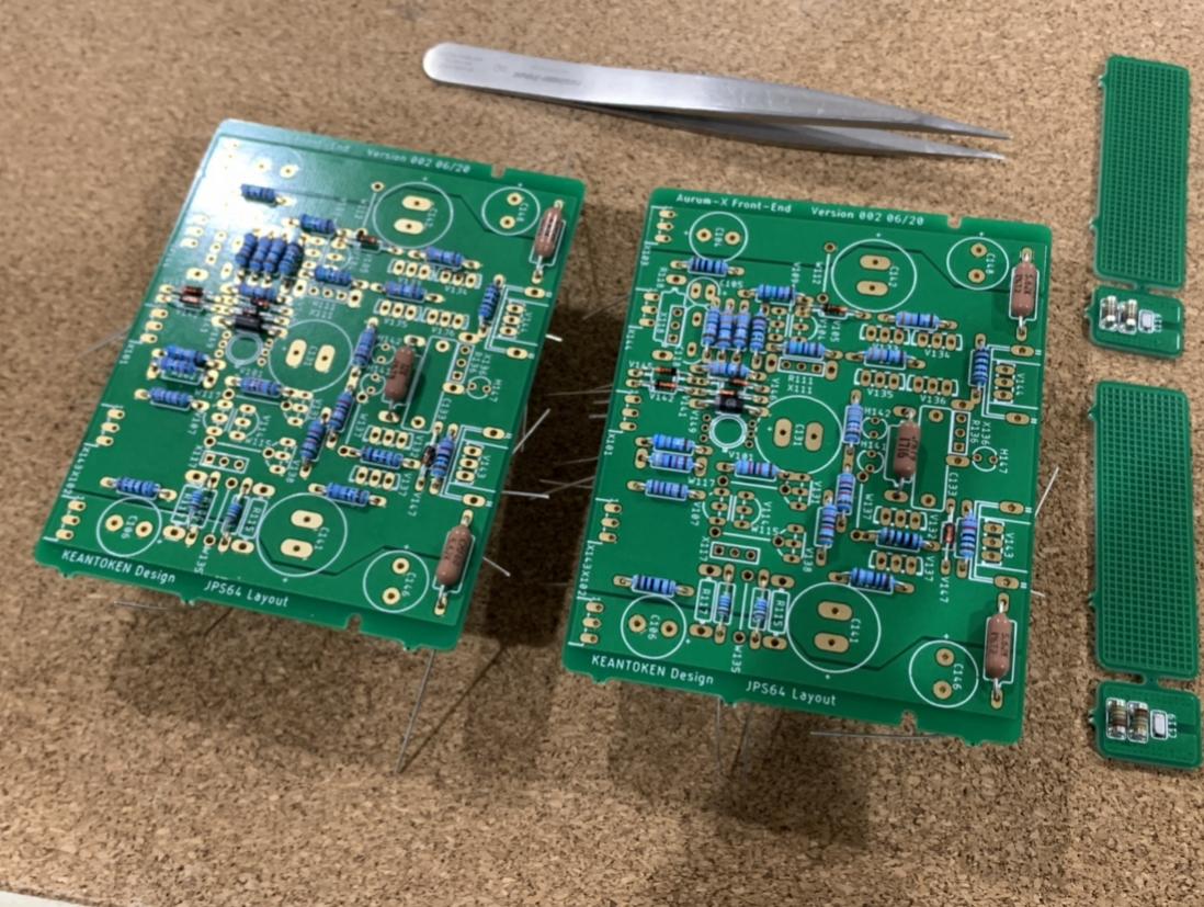
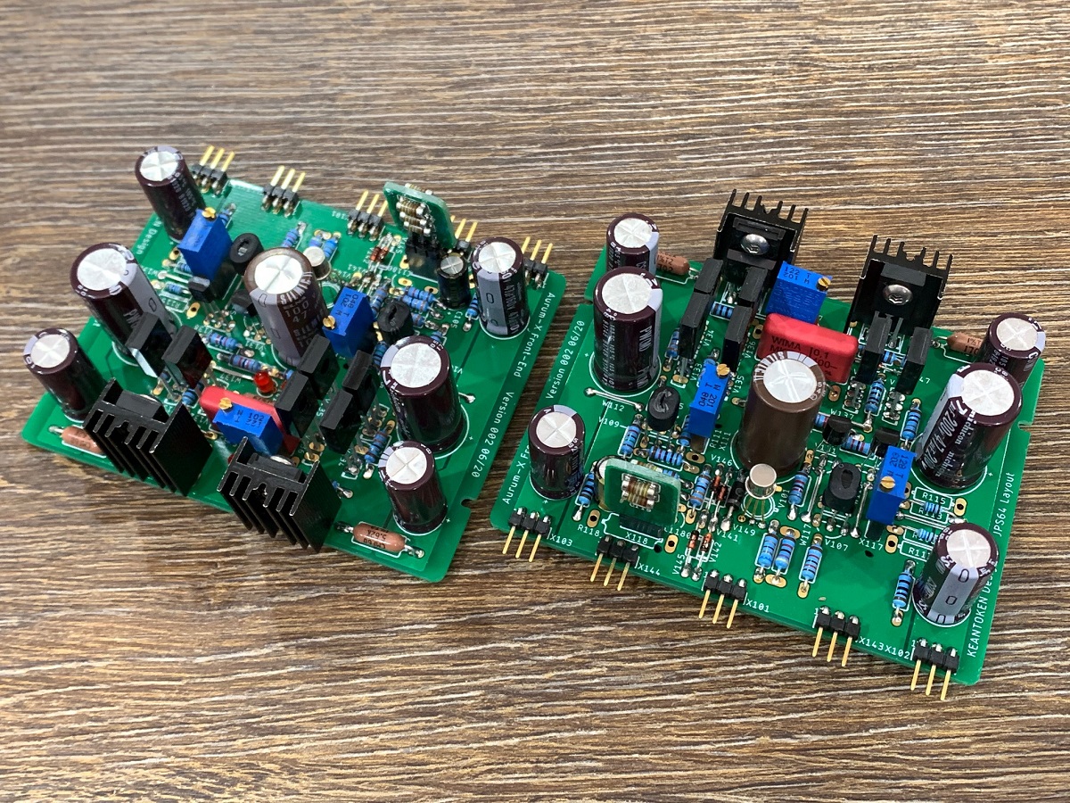
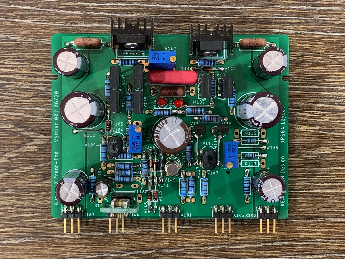
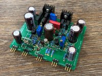
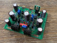
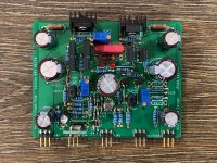
The FE boards are now built. Need to test them next out in the open with a +/-80v power supply. Adjust the bias and DC offset. Somehow the TTA006B driver got left off the order so I am using 2SA1837's in its place (BCE/ECB pins had to be flipped). There are three places with pots mounted on pin header sockets so that after adjustment, they can be removed and replaced with fixed resistors. The KSC1845's and KSC3503's were all matched for Hfe. The KSC1845's are also thermally bonded together to track better. The drivers have little aluminum bolt on heatsinks.


Keantoken,
what is the best way to test these FE's on the bench? Provide +/-80v, ground input and adjust pots to get proper bias currents in VAS and DC offset should be minimized. If you can tell me the key things to look for when testing that would be helpful. Once DC settings are set properly I can take a look at signal in and out on an O-scope.
Thanks,
X
Attachments
Last edited:
Sorry for being late with this.
The driver bootstraps should be connected to the feedback point if you test the frontend without the outputs.
I watch the feedback point on the oscilloscope as I power it up. Bring it up slowly first if you can. You can expect the output to peg to one or the other rail at first as there are multiple time constants at play during startup.
If that goes well and the output settles at 0V, you can touch the input with a DMM probe and see if you get amplified hum on the output. That is a pretty quick functional test.
At this point you can try several cycles of a hard power on and check that the output still settles at 0V and amplifies hum.
At that point I would hook up the signal generator and do sine and square wave tests. Sine to clipping, to make sure there is no latching behavior, and square wave to see if slewing is reasonably symmetrical.
You can expect stability to not be perfect since the output stage is part of the feedback tuning. You can try reducing the feedback pF capacitor if it doesn't want to be stable without the output stage.
I was hoping to be able to test the FE boards by themselves but my SMPS was not able to provide sufficient current or went into hiccup mode at startup. That requires getting the rest of the parts done the main board and populating it before I can test using the real full size trafo (which I have). But other (paid) work is getting in the way and keeping me super busy that it’s hard to find time to do this. I may have to ask a friend to take over the verification build stage for me at this point if I want to get it going again. Thanks for asking though.
I have asked Vunce to help me with assembling the verification build and he has agreed. Maybe we can get some progress afterall. I have just been too tied up with work to take on a big project like this lately.
Thank you, Vunce!
Thank you, Vunce!

Not sure what you mean by "dual mirror". The idea for this design was to take what it is about the original that people like, and not screw it up while upgrading the design. I could have just gone after bigger and better numbers, but the design would have been unrecognizable from what it started out as.
- Home
- Group Buys
- Aurum-X 300w Class AB Amp GB