GB 2 status update:
Three folks in the pledge list still have not responded with preorders yet.
xrk971 20 units USA *Yes*
Mordikai 2 units USA *Pre-order Placed*
Rtep2007 1 unit CZR *Pre-order Placed*
Blossom 1 unit NZ
jrosser 1 unit UK
redjr 1 unit USA *Pre-order Placed*
StuntFingers 1 unit UK *Pre-order Placed*
Atohmdiy 1 unit *Yes*
Tommost 1 unit *Pre-order Placed*
wineds 1 unit AUS *Pre-order Placed*
Three folks in the pledge list still have not responded with preorders yet.
Thanks for your order MaxxPower.
xrk971 22 units USA *Yes*
Mordikai 2 units USA *Pre-order Placed*
Rtep2007 1 unit CZR *Pre-order Placed*
redjr 1 unit USA *Pre-order Placed*
StuntFingers 1 unit UK *Pre-order Placed*
Tommost 1 unit *Pre-order Placed*
wineds 1 unit AUS *Pre-order Placed*
MaxxPower 1 unit USA *Pre-order Placed*
I just got word that the verifcation builds will be started and hopefully done by end this week, we can proceed with the production run after these are deemed successful.
Awesome. Thanks for the update and I look forward to it.
Depending on the thermal spacer on the bottom side to conduct heat away or maybe you will use a small heatsink with a fan, give your self at least 75mm internal height. Actual height from thermal pad on top of TPA3255 mounted on bottom to top of main PSU rail caps is 55mm.
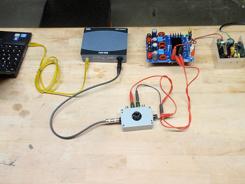
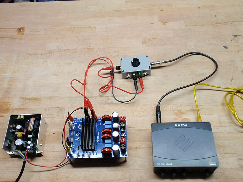
How to do a good/clean test setup (by Voltwide):
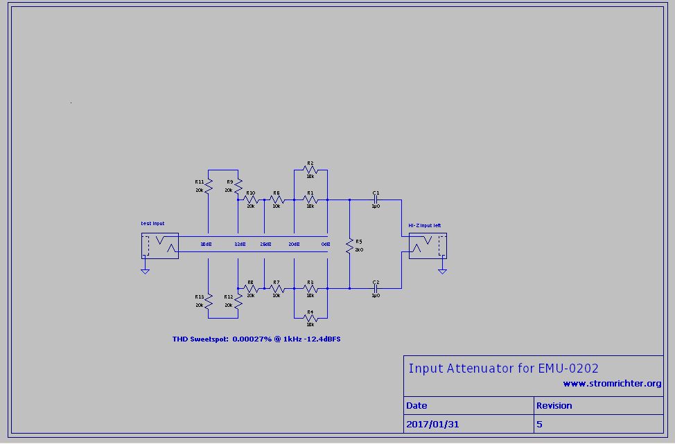
Possible attentuator (by Voltwide):
I'm having some trouble matching the attenuator schematic with the attenuator connections shown in the pictures. The attenuator output to the USB soundcard input seems straightforward (3 -wire, differential), but I'm having trouble decoding the 3 connectors on the attenuator input side. I assume the plus and minus amp outputs would be connected to the plus and minus differential inputs and the ground on the input side would be left unconnected. But I see a third connector on the attenuator I didn't expect to see. Any clarification would be appreciated.
Thanks....
drawn with LTSpice this schematics is simplified. Add a 5position rotary switch with 2 contacts not explicitely shwon in the drawing.
Both busses from the stereo phone jack are connected to both wipers of the rotary switch. The taps of the resistor divider are connected to the according taps of the rotary switch.
Hope that explains it")
The fotograph on top shows a noise measurement: There are shorting plugs on the cinch inputs of the EVM. In that case there is no connection between soundcard output and EVM input. This requires an explicit gnd connection between soundcard and DUT: one red wire was connected to EVM-Power-Gnd.
Both busses from the stereo phone jack are connected to both wipers of the rotary switch. The taps of the resistor divider are connected to the according taps of the rotary switch.
Hope that explains it
Normally ground is connected on the soundcard input side of the attenuator but not connected on the power input of the attenuatorI'm having some trouble matching the attenuator schematic with the attenuator connections shown in the pictures. The attenuator output to the USB soundcard input seems straightforward (3 -wire, differential), but I'm having trouble decoding the 3 connectors on the attenuator input side. I assume the plus and minus amp outputs would be connected to the plus and minus differential inputs and the ground on the input side would be left unconnected. But I see a third connector on the attenuator I didn't expect to see. Any clarification would be appreciated.
Thanks....
The fotograph on top shows a noise measurement: There are shorting plugs on the cinch inputs of the EVM. In that case there is no connection between soundcard output and EVM input. This requires an explicit gnd connection between soundcard and DUT: one red wire was connected to EVM-Power-Gnd.
Depending on the thermal spacer on the bottom side to conduct heat away or maybe you will use a small heatsink with a fan, give your self at least 75mm internal height. Actual height from thermal pad on top of TPA3255 mounted on bottom to top of main PSU rail caps is 55mm.
Thanks. Do you have any dimensions for the thermal spacer? Hole size and locations? I have some 12x3mm aluminium bar. Could I use that?
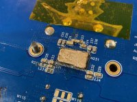
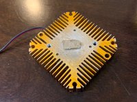
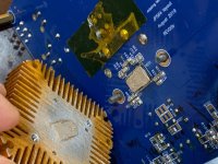
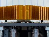
The two holes for mounting the bottom side heatsink or thermal pad spacer are 3mm dia holes spaced 36mm apart ctc. A 12mm wide x 3mm thick aluminum strip can work but note that there needs to be either a small elevated mesa on the flat surface to provide clearance for the SMT capacities mounted nearby as they are slightly higher than the TPA3255 chip. Conveniently, a copper core TE Connectivity Faston tab has the right dimensions of just covering the thermal pad of the TPA3255 and not being bigger than the width of the chip. I snipped the TH solder leg ends of the Faston tab off. I am actually using two of them to give about 2mm clearance between the heatsink and the IC. For testing I am using a small fan cooled GPU cooler with 12v fan. I added a 2W 100R resistor in series with the fan lead to slow it down to almost inaudible levels. The main amp has a 12v power output that I tapped off. It doesn’t seem to cause any motor noise pickup issues based on FFTs that I have seen.
Make sure you use thermal heatsink paste between the spacers and chip and heatsink. On a build where the thermal pad will be connected to a grounded chassis, make sure you use a non conductive insulator pad to prevent the thermal pad ground from directly contacting chassis ground to prevent ground loop hum. Ceramic insulator spacers are good for this. They are more thermally conductive than silicone and tougher. However, silicone can work fine. We are not talking about a huge load unless you plan on running full bore 200w per channel rms. In that case, 20w per channel or 40w total must be dissipated from that pad assuming 90% thermal efficiency. 40w is on the high end of even a typical TO247 MOSFET running in Class A. But normal music listening levels of say 40wrms is only 4w and is nothing for this type of thermal pad.
Some photos of how I installed my Faston thermal pad with a fan cooled heatsink are below.
Attachments
Last edited:
- Home
- Group Buys
- TPA3255 Reference Design Class D Amp GB