Nice work Tumaru! You need a mint tin!")
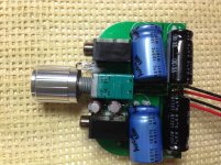
Caps upright instead of on their sides. I can't put it in the mint case. I have it on a necklace around my neck right now as a proof of concept. I might have custom wood cases made.
Would love to see your design, Needtubes. If you can offer this to the DIY community that would be great.
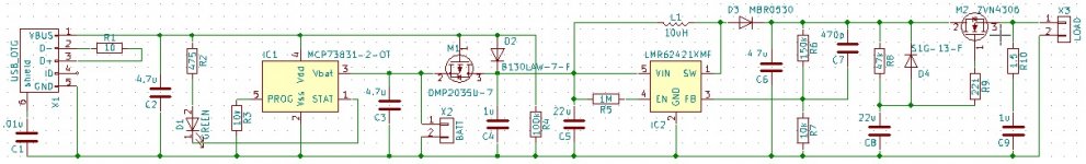
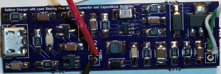
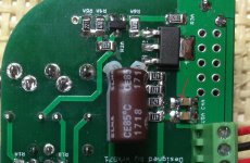
Got my prototype USB charger > DC boost > cap multiplier boards from OSH Park on Friday, so was able to get one stuffed and tested. Sure is tough to solder .025" pitch micro-USB connectors by hand! Everything appears to work fine, though I have convinced the board to complain audibly at times (whine emitted from the board itself). Seems the TI DC boost converter doesn't like it when the input voltage gets much higher than 5V when under heavy load. I changed one resistor value and it seems better now, though. With the part values shown on my schematic, I get 18.4V to my headphone amp which draws ~40mA, and 17V to my headphone amp which draws ~90mA. Efficiency around 80% (calculated in situ with the 40mA draw amp).
Credit for the USB charger with load sharing goes to Zak Kemble. The DC boost converter comes, essentially, from the TI datasheet, although I have changed one resistor value for slightly higher output voltage and plan to change the compensation capacitor value to see if that fixes the occasional whine. The capacitance multiplier has been seen many places, by many people, including Nelson Pass, juma, xrk971, and others (I've previously used a version with IRF510 as well). Layout is entirely my own. Board is 56.2mm x 17.2mm, so it basically fits perfectly across an Altoids tin.
Will test more fully soon, now that I've salvaged some Li-ion cells from an old laptop.
Attachments
Last edited:
The micro USB jacks are so convenient in use, but a pain to build with. Dousing it in liquid flux and using a flat soldering iron tip did the trick on the tiny pins for me. Raptor spec'd a jack that needed to have the bottom slot tabs clipped off in order to be mounted SMD style on an OSH (no slots) board. I did this and then tacked the jack to the board using the pads on both sides. And yet a few days ago I managed to break the jack loose from the board after plugging/unplugging (carefully!) less than 30 times. Now it's just hanging by the pins and of course intermittently cutting out. If yours is also mounted this way, treat it gingerly!
Last edited:
Thank you, xrk. I've tested a bit more with my Li-ion cell, and it is running fine. Will try to give it a good test tomorrow, after I give my battery a chance to charge. How long do you typically have to charge the battery using Kemble's charging circuit?
Solder paste sounds like a good idea for the micro-USB pins. I used my needle-point tip with .015" solder and managed to very carefully connect each pin.
OSH Park warned me about the slots when I initially uploaded the design, so I modified the footprint for round holes instead of slots. The bottom mounting pins are functional on my boards. Hopefully that will make the connector more secure long-term, but only time will tell...
If there is interest in these boards, I can look into getting a run of them made. Or, if someone wants to "beta test" first, you can PM me about a board. I have two left, but would probably only let one go for now.
Solder paste sounds like a good idea for the micro-USB pins. I used my needle-point tip with .015" solder and managed to very carefully connect each pin.
Raptor spec'd a jack that needed to have the bottom slot tabs clipped off in order to be mounted SMD style on an OSH (no slots) board.
OSH Park warned me about the slots when I initially uploaded the design, so I modified the footprint for round holes instead of slots. The bottom mounting pins are functional on my boards. Hopefully that will make the connector more secure long-term, but only time will tell...
If there is interest in these boards, I can look into getting a run of them made. Or, if someone wants to "beta test" first, you can PM me about a board. I have two left, but would probably only let one go for now.
Sorry you are having problems Freebee. What type of batteries are you using? Sometimes the Li-ion rechargeables need to be clicked on-off quickly 2-3 times to partially charge rail caps to prevent in-rush current shutdown of battery smart circuitry. Is LED polarity wired correctly? When no LED lights up, first thing to check is power supply or battery.
If you can measure power applied to the rail caps (circa 16v to 18v) next measure bias current through R7 array. Then current through R3. Voltage across R7 should be between 6.5v to 7.5v. Voltage across R3 should be about 3v to 4v IiRC. If 0v on R3 look for cold solder joints in main cluster of R1-R5. If voltage at gate of MOSFETs is high (same as pin 2) but voltage across R7 (pin 3) is zero, you probably have a static electricity zapped MOSFET.
If you can measure power applied to the rail caps (circa 16v to 18v) next measure bias current through R7 array. Then current through R3. Voltage across R7 should be between 6.5v to 7.5v. Voltage across R3 should be about 3v to 4v IiRC. If 0v on R3 look for cold solder joints in main cluster of R1-R5. If voltage at gate of MOSFETs is high (same as pin 2) but voltage across R7 (pin 3) is zero, you probably have a static electricity zapped MOSFET.
Last edited:
measured 18v on both rail caps. How do I measure R7 array? I don't get any results. R3 is 11v on both.
Positive DVM probe on MOSFET pin 3 and negative DVM probe on GND (top of array close to battery jack).
R3 with 11v sounds odd. What is voltage at Pin 1 of MOSFET (relative to ground)? What is Pin 1 relative to rail cap 18v?
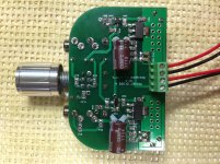
One other thing to check is do you have your input and output 3.5mm connected in correct order? With SMT side up and volume pot facing you, audio input goes to 3.5mm jack on LEFT jack and headphones on RIGHT jack.
I have done this a few times and it is absolutely silent when audio source goes in to RIGHT jack and headphones on LEFT jack
You have voltage so I think LED is backwards.
Last edited:
hi there, Just which way should the led go? Minus at the front and plus at the back? Will measure the rest as suggested. Batteries are 2x 9v Li-ion 1000 mAh rechargables. Thanks for your help.
The flat (cathode) of the LED should go to the hole closest to the edge (GND). Current flows from positive (Anode or long pin and rounded side) to negative (Cathode or flat side).
It sounds like your batteries may have something strange going on with self-protect circuitry built inside. Try alkaline non rechargeable 9v batteries and see if LED stays lit. The other possible cause is that the MOSFETs burned out in shorted mode and conduct too much current, hence cause batteru shutdown. What is resistance in ohms between pins 2- & 3 after amp turned off and all caps discharged?
764 ohm on both sides. I hope I discharged the caps fully with a resistor 180R cement resistor.
The 764ohm is ok - I get about 850ohm. It shows open circuit at first, then slowly goes from Mohm to 1.4kohm then slowly drops to 850ohm. So that looks ok - your MOSFETs are still intact it seems.
Led (2000mcd 470nm) seems to be in the correct position (-) cathode on the edge/front of the board. Mosfet pin 3 to ground gives no result. Pin 1 to ground gives about 3.76v however. Pin 1 to negative cap rail 3.76v as well. R3 is 12.4v.
There is about 6.5v to 7v drop across R3 so that looks like your JFETs are getting the proper 7mA bias current. Means they are notdead. Pin 1 of MOSFET should be around 7v to 7.6v. You have 3.76v and that is low. It is low because something is sucking all the current. You have a shorted component somewhere.
At this point all I can think is that you have a bad solder joint somewhere or a short (caused by residual solder under the SMT resistor or capacitor) making it 0ohm. This happened one time on an amp and it turned out to be a shorted bypass cap (C4A and C5A and C5A C5B - the two next to the R7 array). Take DMM and check ohms across the X7R bypass caps. It should read open circuit and not close to 0ohms. If so, resolder and remove excess solder. Check all resistors for shorts.
Check especially where red arrow is for short to GND.
Attachments
Last edited:
- Home
- Group Buys
- xrk971 Pocket Class A Headamp GB