Hi again! You were right about the batteries. Somehow it doesn't like Chinese ") . Have another Chinese dish on offer which hopefully it'll like!
. Have another Chinese dish on offer which hopefully it'll like!
In the meantime I got sound and LED stayed on with Alkaline batteries.
I have one more question (for the moment)...
I fitted 1uf on C2_2, however I haven't fitted 2.2uf yet. Am I correct in thinking both caps are bypassing C2_1? I fitted Silmic's, but also have WIMAs. Which are best in this configuration?
Thanks again for all your hard work!!!
. Have another Chinese dish on offer which hopefully it'll like! In the meantime I got sound and LED stayed on with Alkaline batteries.
I have one more question (for the moment
)...I fitted 1uf on C2_2, however I haven't fitted 2.2uf yet. Am I correct in thinking both caps are bypassing C2_1? I fitted Silmic's, but also have WIMAs. Which are best in this configuration?
Thanks again for all your hard work!!!
something slightly unrelated, but just wanted to update here.
I wanted to make an output cap bank, goals being relatively small size but customizable with required capacitance.
able to take stereo channels. I have this status ob-1 paired with ESP HPA. and x suggested this way to protect the phones.
I have ordered cap bank pcbs today and if anyone is interested they can also order here
output cap bank (2)- Share Project - PCBWay
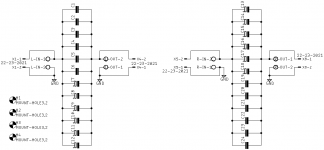
or can have it from me , once I build and test it. I plan to use NP caps bypassed with film caps. 6 x 220u 25V and 4x 1u Film.
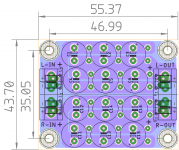
the board can take 10mm dia caps and 1 to 2u2 film caps.
The caps can be fitted both on top as well as bottom. electrolytic can also be fitted on bottom.
Soldering sequence is very important. Top row followed by bottom row and so on until you achieve required value.
One could also use normal electrolytics, but back to back for split supply. So its flexible.
here is the sch, top view and bottom flipped view.
regards
Prasi
I wanted to make an output cap bank, goals being relatively small size but customizable with required capacitance.
able to take stereo channels. I have this status ob-1 paired with ESP HPA. and x suggested this way to protect the phones.
I have ordered cap bank pcbs today and if anyone is interested they can also order here
output cap bank (2)- Share Project - PCBWay
or can have it from me , once I build and test it. I plan to use NP caps bypassed with film caps. 6 x 220u 25V and 4x 1u Film.
the board can take 10mm dia caps and 1 to 2u2 film caps.
The caps can be fitted both on top as well as bottom. electrolytic can also be fitted on bottom.
Soldering sequence is very important. Top row followed by bottom row and so on until you achieve required value.
One could also use normal electrolytics, but back to back for split supply. So its flexible.
here is the sch, top view and bottom flipped view.
regards
Prasi
Attachments
Hi again! You were right about the batteries. Somehow it doesn't like Chinese
In the meantime I got sound and LED stayed on with Alkaline batteries.
I have one more question (for the moment
I fitted 1uf on C2_2, however I haven't fitted 2.2uf yet. Am I correct in thinking both caps are bypassing C2_1? I fitted Silmic's, but also have WIMAs. Which are best in this configuration?
Thanks again for all your hard work!!!
Great news, so nothing wrong with the amp then. I should make a note to have first sound test with non rechargeable batteries.
Silmics don't need to be bypassed - but you are welcome to. Probably 0.47uF to 1uF film cap is all that is needed. If no Silmic 10uF on input use at least 2.2uF for best deep bass response.
something slightly unrelated, but just wanted to update here.
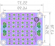
I wanted to make an output cap bank, goals being relatively small size but customizable with required capacitance.
able to take stereo channels. I have this status ob-1 paired with ESP HPA. and x suggested this way to protect the phones.
I have ordered cap bank pcbs today and if anyone is interested they can also order here
output cap bank (2)- Share Project - PCBWay
or can have it from me , once I build and test it. I plan to use NP caps bypassed with film caps. 6 x 220u 25V and 4x 1u Film.
the board can take 10mm dia caps and 1 to 2u2 film caps.
The caps can be fitted both on top as well as bottom. electrolytic can also be fitted on bottom.
Soldering sequence is very important. Top row followed by bottom row and so on until you achieve required value.
One could also use normal electrolytics, but back to back for split supply. So its flexible.
here is the sch, top view and bottom flipped view.
regards
Prasi
Nice one Prasi! You should post in the ESP HPA thread as well.
Got my prototype USB charger > DC boost > cap multiplier boards from OSH Park on Friday...
...Will test more fully soon, now that I've salvaged some Li-ion cells from an old laptop.
My amp spent a week in my office with the new power supply board installed. Every feature works great.
I haven't heard from anyone regarding interest in trying my boards, so I suppose there isn't much (if any). Or, perhaps people were waiting for the report on functionality. Either way, thought I would report for the sake of completion.
No, I haven't posted Gerbers. I was thinking more along the lines of retaining my Gerbers and running a group buy.
Would you be willing to "beta test" before we all commit to a run of the boards? I have confirmed that my board is working fine, but would feel better about releasing boards to the public after an independent test.
Would you be willing to "beta test" before we all commit to a run of the boards? I have confirmed that my board is working fine, but would feel better about releasing boards to the public after an independent test.
I am interested in getting 2 pcb if you start gb. Haven't assembled the amp but don't like 9v charging time. so it's good timing if you can start gb soon.My amp spent a week in my office with the new power supply board installed. Every feature works great.
I haven't heard from anyone regarding interest in trying my boards, so I suppose there isn't much (if any). Or, perhaps people were waiting for the report on functionality. Either way, thought I would report for the sake of completion.

Getting there
View attachment 661812
Edit: yes, the heatsinks look like they're on the bottom of the board. You can ignore that, I put the outline there cos it's irritating when working on the layout.
Hi BDHM,
Hope all is well - haven’t heard from you in a while. How is the desktop amp coming along?
Thanks so much,
X
Hi BDHM,
Hope all is well - haven’t heard from you in a while. How is the desktop amp coming along?
Thanks so much,
X
Barring any additional requests or input, I reckon we're good to go
. Any luck finding a suitable inductor?Thanks for reminding me about the inductor. Still looking so perhaps maybe we just put a couple of pads for soldering flying leads to a TBD inductor (mounted off the board) but leave space around pads spaced 25mm pitch for something approximately the size of a 65mm square to reserve space for a 2.4in Dia donut. I have heard that small 10W toroidal power trafos can be used as audio chokes. Need to test out though as they never specify the inductance of the primary or secondary. If space is too large we can always go off-board and keep PCB more compact.
Here is a trafo I am considering to use as choke.
AN-0106 - 10VA 6V Transformer - AnTek Products Corp
Here is a trafo I am considering to use as choke.
AN-0106 - 10VA 6V Transformer - AnTek Products Corp
Still looking so perhaps maybe we just put a couple of pads for soldering flying leads to a TBD inductor (mounted off the board) but leave space around pads spaced 25mm pitch for something approximately the size of a 65mm square to reserve space for a 2.4in Dia donut. ... If space is too large we can always go off-board and keep PCB more compact.
Two 60mm toroids are gonna take up a lot of board real estate
. Looking at either much wider (250mm) or a fair bit longer (170mm)- Home
- Group Buys
- xrk971 Pocket Class A Headamp GB