THIS GROUP BUY CLOSED ON Dec.2, 2014. (for the newly interested see post #98)
i.) this is a limited time offer for ordering pcb by year end (say X-mass time? ).
).
ii.) one channel per board. the cost is tbd based on number of boards (absolutely no interest for me other than lowering the price for my 4 pieces).
iii.) reg PS section may be added to this board with a break away option, or ordered as a separate piece (we can decide together and I can add this section later).
iv.) I usually order from pcbcart in china and the board will be green with white silkscreen (other colors cost more).
p.s. all components are through hole but you still need solid soldering skills (i.e. you cannot solder with a log for the soldering tip).
vi.) this board has not been tested and you share the risk with me.
about AlephP v1.7: just a few reminders about the preamp: well, it is Papa's design. It can handle both unbalanced and balanced inputs and outputs independently (so also an ideal converter from one to the other). it runs on higher voltage (60V reg), which makes getting lower noise figures easier but it also makes the pre not a good choice for an integrated amp and sharing amp PS at say +-24V. The max output of 20V is short of driving a bal F4 or similar output stage to max power. Papa also made an unusual choice to drive a stepped relay attenuator at preamp output (good for pre noise suppression but requires a few attenuator steps at pre input to prevent saturation with hot sources). the biggest drawback: Papa voiced AlephP with the big and expensive Wima MKP caps . those are rare pieces for which the manufacturer actually provided data as tested over the full audio spectrum. I guess Papa values his time and only works with the best of the components, (and I sort of share the same philosophy when it comes to my time ). (later edit: actually it looks like the commercial AlephP did not use Wimas).
about PCB: I considered briefly the board which sold many pieces on this forum. well: a huge rail-to-gnd loop for picking up noise, but more importantly, Wimas do not fit there and I will be using those; (I can provide an alternative footprint for you though); Moreover I wanted to use REED relays for the best contact quality possible on those input attenuators, and also for shorting neg signal to Gnd if used as unbalanced on either input or output. So I put together a two sided board, solid copper pour for ground (also EMC protection, kind of overkill for audio but that's DIY, right?). mind you: relays require a 5V PS (not provided). in my case the relay selections are made via a 4-pole DIP switch on the board, (or you can wire front mounted switches if that's what you want). the input attenuator relay is a common Hamlin HE700 series (DPST-NO); the other one is a relay i bought as surplus stock (Spartan 9000) and you may have to look up a replacement for the footprint. Of course, you can also give up either relay and just jump the contacts with a wire.
footnote: 5V PS and 1kOhm relay attenuator with remote control can be purchased from Mikkel (dantimax.dk). or any other source for that matter; you're on your own there.
here is the image of the board. please state your interest here. Thanks.
p.s. (I will also consider comments on the board, but you already know that every layout is about compromizes).

later edit: for build details see another thread:
http://www.diyaudio.com/forums/pass-labs/239072-pass-aleph-p-1-7-preamp-builders-thread-31.html#post4335587
i.) this is a limited time offer for ordering pcb by year end (say X-mass time?
).ii.) one channel per board. the cost is tbd based on number of boards (absolutely no interest for me other than lowering the price for my 4 pieces).
iii.) reg PS section may be added to this board with a break away option, or ordered as a separate piece (we can decide together and I can add this section later).
iv.) I usually order from pcbcart in china and the board will be green with white silkscreen (other colors cost more).
p.s. all components are through hole but you still need solid soldering skills (i.e. you cannot solder with a log for the soldering tip).
vi.) this board has not been tested and you share the risk with me.
about AlephP v1.7: just a few reminders about the preamp: well, it is Papa's design. It can handle both unbalanced and balanced inputs and outputs independently (so also an ideal converter from one to the other). it runs on higher voltage (60V reg), which makes getting lower noise figures easier but it also makes the pre not a good choice for an integrated amp and sharing amp PS at say +-24V. The max output of 20V is short of driving a bal F4 or similar output stage to max power. Papa also made an unusual choice to drive a stepped relay attenuator at preamp output (good for pre noise suppression but requires a few attenuator steps at pre input to prevent saturation with hot sources). the biggest drawback: Papa voiced AlephP with the big and expensive Wima MKP caps
. those are rare pieces for which the manufacturer actually provided data as tested over the full audio spectrum. I guess Papa values his time and only works with the best of the components, (and I sort of share the same philosophy when it comes to my time ). (later edit: actually it looks like the commercial AlephP did not use Wimas).about PCB: I considered briefly the board which sold many pieces on this forum. well: a huge rail-to-gnd loop for picking up noise, but more importantly, Wimas do not fit there and I will be using those; (I can provide an alternative footprint for you though); Moreover I wanted to use REED relays for the best contact quality possible on those input attenuators, and also for shorting neg signal to Gnd if used as unbalanced on either input or output. So I put together a two sided board, solid copper pour for ground (also EMC protection, kind of overkill for audio but that's DIY, right?). mind you: relays require a 5V PS (not provided). in my case the relay selections are made via a 4-pole DIP switch on the board, (or you can wire front mounted switches if that's what you want). the input attenuator relay is a common Hamlin HE700 series (DPST-NO); the other one is a relay i bought as surplus stock (Spartan 9000) and you may have to look up a replacement for the footprint. Of course, you can also give up either relay and just jump the contacts with a wire.
footnote: 5V PS and 1kOhm relay attenuator with remote control can be purchased from Mikkel (dantimax.dk). or any other source for that matter; you're on your own there.
here is the image of the board. please state your interest here. Thanks.
p.s. (I will also consider comments on the board, but you already know that every layout is about compromizes).
later edit: for build details see another thread:
http://www.diyaudio.com/forums/pass-labs/239072-pass-aleph-p-1-7-preamp-builders-thread-31.html#post4335587
Last edited:
I'm interested. Rough board pricing?
Do you have a source for the caps? Assuming 37.5 mm lead spacing Mouser US is showing enough on order to build a half dozen Aleph P1.7s, but half won't get caps until next September. Newark has 6.8 µF in stock for a lot less than Mouser's 10 µF. But again, not enough to build many. Perhaps enlarging the board to accept 2 input caps and 5 outputs will allow reaching the appropriate total value at lower cost/better availability.
EDIT: Good point Yoke, there should be some heat sinking with 60V rails unless we keep the current very low.
four irf610s are back-to-back at 1/8" inch to share a 3mm thick heatsink (I usually just bend a copper strip in an "S" kind of shape over the low components around. I can post an example pic later today). the two 9610s are also to share a 2-2.5mm thick heatsink back to back. I do not expect much need with current sources at 20 and 30 mA.
about caps: i will be using the big Wimas (MKP4/250V P:37.5; body: 19x42x32H). I bought a bunch from Conrad when on business in Germany (well, I ran out of time at the airport and never got the european VAT back, so it did not end up a great deal after all, but that's a different story). i can provide one (or maybe two) alternative footprint(s) if a bunch agrees on a common cap. one should probably be the cheapo option of electrolityc SilmicII with a 100nf film bypass cap (kind of waisting board space there); and the other could be an other-than-Wima PP (with just a different pitch)?
p.s. btw I will make one stereo AlephP for sure, and the other I may be selling as a full kit (not quite sure yet).
p.s2. as for stacking the boards on top of each other: i make no special accomodation there. too many big components to play with mirror images and such, so they'll just have to add up fully in height.
on pcb layout
btw the only thing I am not happy with is a little waisted space in the middle between large caps, so I may end up putting a smiley face logo there?.
Maybe (and that's a ??) I could make it a bit more compact by putting all caps together and moving the middle section to the end of the board and sqeezing it together with the remaining four resistors and two screwholes; the relay footprint is cumbersome to work with, and the traces across the board will become long. after all, no layout will ever be perfect so there is always a question of effort versus returns. this admittedly would be better if a regulator section followed at the end of board and only for those who would not separate it, (mind you keeping PS there would make for one long board though).
btw the pcb screw holes are for number4 or M3 screws.
p.s. no idea of price before the final count: if of any consolation to you I paid $132 for two prototype boards for a digital fan control/soft start/spk protection a friend of mine helped me develop. but the price drops quickly when ordering more. $15-20/piece should be a reasonable target? whatever it will be, I will share the cost off the vendor's site with the group and just divide by piece count.
btw the only thing I am not happy with is a little waisted space in the middle between large caps, so I may end up putting a smiley face logo there
?. Maybe (and that's a ??) I could make it a bit more compact by putting all caps together and moving the middle section to the end of the board and sqeezing it together with the remaining four resistors and two screwholes; the relay footprint is cumbersome to work with, and the traces across the board will become long. after all, no layout will ever be perfect so there is always a question of effort versus returns. this admittedly would be better if a regulator section followed at the end of board and only for those who would not separate it, (mind you keeping PS there would make for one long board though).
btw the pcb screw holes are for number4 or M3 screws.
p.s. no idea of price before the final count: if of any consolation to you I paid $132 for two prototype boards for a digital fan control/soft start/spk protection a friend of mine helped me develop. but the price drops quickly when ordering more. $15-20/piece should be a reasonable target? whatever it will be, I will share the cost off the vendor's site with the group and just divide by piece count.
Last edited:
Hello,
I`m also interested in probably 6-8 pcb`s, dependent on price..
Also if possible:
Caps: if room, please add trace for larger "boutique" caps
Jensen is Ø46x70mm long
Mundorf is Ø45x70mm long
Obligato is Ø30x75mm long etc
Relay:
Please post model no of relays, so we can be shure it is awailable, and not "end of life", or obsolite like Reed 9081C-12-10. Reed 9007-12-40 is "non stocked" at Mouser..and they come up when searching for Spartan 9000.... If you are doing the work, I am hoping your design can be buildt in the near future also..
It will be easier to sell boards if the parts are available from many sources.
I am also fan of gold or silver over lead/copper contacts in realay`s..
Thank you for doing the work with the pcb!
Ok, it is already clear that it will not be possible to please everybody.
those boutique caps are huge and I cannot blow the whole pcb to that size. Sorry. (If more people are into those I may eventually consider doing something for you only, as a forum favor, but not right now). Wima is the base cap; if that one is not for you aim at something that can fit within those outlines, only pitch may be different.
I realize already that the Spartan relay may have to change for a more available one, (not good for me because I packed everything so tight on the pcb there ). otherwise, any Reed relay, (gold or not but with vacuum preventing oxidation) will garantee superb contact quality over a long time.
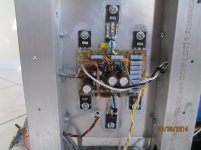
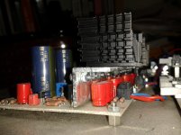
anyways, I promised Yoke to show the example of how I go about cooling the fets. here I show the pic of my aleph30 board where three 9610s share a copper strip. on AlephP board something along those lines will be possible as well. (maybe a "T" shape aluminum channel with some holes on top?) your imagination is the limit. be warned: if I like yours better I may copy you.
those boutique caps are huge and I cannot blow the whole pcb to that size. Sorry. (If more people are into those I may eventually consider doing something for you only, as a forum favor, but not right now). Wima is the base cap; if that one is not for you aim at something that can fit within those outlines, only pitch may be different.
I realize already that the Spartan relay may have to change for a more available one, (not good for me because I packed everything so tight on the pcb there
). otherwise, any Reed relay, (gold or not but with vacuum preventing oxidation) will garantee superb contact quality over a long time.anyways, I promised Yoke to show the example of how I go about cooling the fets. here I show the pic of my aleph30 board where three 9610s share a copper strip. on AlephP board something along those lines will be possible as well. (maybe a "T" shape aluminum channel with some holes on top?) your imagination is the limit. be warned: if I like yours better I may copy you
.Attachments
anyways, I promised Yoke to show the example of how I go about cooling the fets. here I show the pic of my aleph30 board where three 9610s share a copper strip. on AlephP board something along those lines will be possible as well. (maybe a "T" shape aluminum channel with some holes on top?) your imagination is the limit. be warned: if I like yours better I may copy you
well, this is what comes to my mind, how to solve this...but...will see
with L shape...

p.s...sorry, don't know why is picture this big
Last edited:
Thanks for heat sinking suggestions.
Next questions:
What is the resistor footprint? Can it accommodate larger resistors like Vishay Dale CFM60?
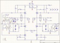
Can you post your schematic so that we can check the board layout? I realize that the changes to the original should only be the attenuator, but it would be handy to have the whole thing on one sheet.
Thanks.
Next questions:
What is the resistor footprint? Can it accommodate larger resistors like Vishay Dale CFM60?
Can you post your schematic so that we can check the board layout? I realize that the changes to the original should only be the attenuator, but it would be handy to have the whole thing on one sheet.
Thanks.
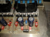
This is how I lay the FETs on my AlephP. I use aluminum L shape profile to attached them to the heatsink. All FETs have their back on a straight line.
I'm using BG-N caps (under the heatsink)... smaller than Wima MKP.
I have designed a PCB using Wima caps and I have bought the MKP... but boy they're big!
I'm using BG-N caps (under the heatsink)... smaller than Wima MKP.
I have designed a PCB using Wima caps and I have bought the MKP... but boy they're big!
Attachments
that heatsink looks like an overkill to me, but it is an inspiration.
the resistors are assumed to fit P:10.35mm; body:6.8(L) x 2.8mm(Diam)
only R44 and R59 (22.1Ohm) off the rail are stood up vertically, and R73 (3.3Ohm/2W) is on a bigger footprint P:20; body: 16.5(L) x 6.5(diam).
btw: the transistors for constant current sources are marked as for ZTX450/550 (as in the original schematic), so if you decide to use BC550c/560c you will need to flip them 180deg since pinout is different.
Attachments
Koja
could you please live some space for capacitors placement...
I'm thinking to buy some wima, and I can find those MKP10 10uF/100 or 250V...the dimensions are ;
MKP10-10U/100 20 x 39.5 x 41.5mm
MKP10-10U/250 24 x 45.5 x 41.5mm
Terminal pitch 37.5mm
I don't know what I will found when the time comes...but would be nice to be safe
and maybe someone could advise me ;
should I go for MKP10 vs MKP4 for this aplication ?
Last edited:
since you are only to buy those caps, i.e. you do not have them yet, (like I do, all 40 of them), the answer is simple: MKP4 (pcb is already set up for those, so no changes for the sake of changing). i already stated: only an alternative pitch could be offered if a few people wanted a cheaper than wima cap and the cap could fit otherwise. no increasing width, length etc. Thanks.
Last edited:
- Status
- This old topic is closed. If you want to reopen this topic, contact a moderator using the "Report Post" button.
- Home
- Group Buys
- Aleph P is back!! (limited time offer)