Hi all,
I'm starting this thread to be a serious discussion on speaker terminal impedance and what it means to frequency response, phase response (or time/group delay), and gain characteristics (or more correctly the transfer function) of a the speaker.
Please, before posting, do the following:
1. Be familiar with the thread. (Understand what's being discussed)
2. Identify Known facts (Physics, Engineering etc.) as such.
3. Cite sources. (Physical Laws, Electrical Laws, Research, etc)
3. Identify Opinions as such. (Please keep these to a minimum)
4. Be respectful of other posters, and discuss disagreements off forum (via private messages, email etc.) before posting. In this case, post a brief description of the disagreement, With both sides following (This can be harder than it seems)
5. When posting personal observations, back them up with physics or engineering, and an explanation of what was noted, and your theory as to why this happened.
I will start the first post, in just a moment...
Measured Impedance
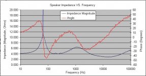
At this point, I will start off by posting an actual graph of measured terminal impedance vs. frequency of a speaker. This graph was created by measuring voltage (Via a TDS3032B O-scope) and Current (Via a TDS3032B and TCP202 Current probe) and the phase relationship between the two, of a swept sine wave (Generated by an Agilent 33220A Signal Generator) into a production speaker (3 drivers, Bass, Mid, and High, including a passive crossover) from 10Hz to 100KHz. (The signal generator, and scope are part of an automated test setup).
This graph was created by taking the voltage and current (including phase relationship) of each frequency point measured and through ohms law (V/I = R) calculating the resultant complex impedance (Magnitude and phase). This impedance was then plotted vs. frequency.
What I first noted in this graph was the impedance bump, at ~68Hz. From my limited understanding of speakers, this is probably the resonant frequency of one of the drivers. (It is possible that it is also an artifact of the crossover).
Please start by posting any observations from the graph, or aspects of the graph worth noting.
Attachments
Re: Measured Impedance
It is actually the system resonance of the bass driver in the box. Given the single peak (and its magnitude) it is likely a sealed box.
As a generalization we can say that the f3 of the box is in the neighborhood of this peak.
dave
dkemppai said:What I first noted in this graph was the impedance bump, at ~68Hz. From my limited understanding of speakers, this is probably the resonant frequency of one of the drivers.
It is actually the system resonance of the bass driver in the box. Given the single peak (and its magnitude) it is likely a sealed box.
As a generalization we can say that the f3 of the box is in the neighborhood of this peak.
dave
The 2nd hump is probably at the mid-woofer crossover.
The phase angle doesn't get too nasty until way high in frequency where there is not a lot of energy so it shouldn't drive the amo too crazy.
(keep in mind that due to the sign term in the power equation, if the phase gets to 90 degrees tha amplifier can no longer deliver any power into the load (since sin 90 = 0, P = 0))
dave
Re: Re: Measured Impedance
Dave,
You are quite right. The speaker is in a sealed box, and it is the resonance of the driver in the system, not free air. (I'm warming up my test system, to run the free air sweep now... ...looks like the Resontant point is 33.9Hz)
At this time, I'm trying to wrap my mind around how mechanical resonance acts in such a way as to reflect reactive impedances back through the speaker terminals. I cannot seem to correlate the mechanical and electrical equivalents. I still have to do some reading on the subject, but am trying to correlate the electrical equivalent to a spring mass system in my own mind.
What I also noted was the leading phase from 10Hz up to the resonant point indicated a capacitive impedance up to the resonant point (If my phases are correct). This seems to make sense, as I remember from RF theory, a short antenna is also appears capacitive, and thus the reason an inductor in series is required to bring the antenna into resonance. Im starting to understand speakers are more of a transmitting antenna than I originally envisioned.
In any case, I'm suspecting that the reactive component of the impedance will affect the ultimate speaker system gain (if you will). In the case of the speaker being driven by a purely voltage feedback amplifier (as most are) the output power vs. frequency (or amplitude, SPL, however you measure it) should be affected by this system impedance. The resultant phase shifts would reduce power delivered to the speaker, and ultimately to the air. This is of course, not taking into account other losses within the speaker system. (This is a truly a ‘system' as you correctly pointed out)
-Dan
By the way. It's nice to see you're still on the boards. It's been awhile since I've been here!
planet10 said:
It is actually the system resonance of the bass driver in the box. Given the single peak (and its magnitude) it is likely a sealed box.
As a generalization we can say that the f3 of the box is in the neighborhood of this peak.
dave
Dave,
You are quite right. The speaker is in a sealed box, and it is the resonance of the driver in the system, not free air. (I'm warming up my test system, to run the free air sweep now... ...looks like the Resontant point is 33.9Hz)
At this time, I'm trying to wrap my mind around how mechanical resonance acts in such a way as to reflect reactive impedances back through the speaker terminals. I cannot seem to correlate the mechanical and electrical equivalents. I still have to do some reading on the subject, but am trying to correlate the electrical equivalent to a spring mass system in my own mind.
What I also noted was the leading phase from 10Hz up to the resonant point indicated a capacitive impedance up to the resonant point (If my phases are correct). This seems to make sense, as I remember from RF theory, a short antenna is also appears capacitive, and thus the reason an inductor in series is required to bring the antenna into resonance. Im starting to understand speakers are more of a transmitting antenna than I originally envisioned.
In any case, I'm suspecting that the reactive component of the impedance will affect the ultimate speaker system gain (if you will). In the case of the speaker being driven by a purely voltage feedback amplifier (as most are) the output power vs. frequency (or amplitude, SPL, however you measure it) should be affected by this system impedance. The resultant phase shifts would reduce power delivered to the speaker, and ultimately to the air. This is of course, not taking into account other losses within the speaker system. (This is a truly a ‘system' as you correctly pointed out)
-Dan
By the way. It's nice to see you're still on the boards. It's been awhile since I've been here!
Attachments
OK, I'll toss this out for thought and comment. First the equations that couple the electrical side to the mechanical side of the driver.
ed = BL ud
fd = BL i
ed = back emf voltage at driver terminals
ud = cone velocity
fd = force on mechanical parts like the cone mass, stiffness, and mechanical damping
i = current in coil due to applied eg
eg = voltage source which will be assumed constant
Below say 100 Hz, the voice coil inductance is small and the resistance is constant. The large peak in the impedance curve is really a reflection of the driver velocity, at resonance the velocity increases. But when the velocity increases so does ud which lowers i for a constant eg. Lower i means less force f so ud decreases. Kind of a control loop which attenuates the driver mechanical resonance so it does not flap back and forth violently and destroy or bottom the suspension.
Bottom line, at low frequencies the impedance curve is really a good measure of driver velocity. Now if you can convert cone velocity into pressure, and thus SPL, you have a complete transformation from electrical input to SPL response. You can use the impedance curve to grapically construct the SPL curve. I have done the math and the graphical exercise but that was years ago and without looking back in my notes I cannot reproduce it off the top of my head.
Hope that helps,
One comment.
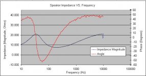
The sharp peak near 50-60Hz looks to me like there is a measurement error, where it really takes off. You can see the slope of the magnitude change abruptly, which should not happen. My guess is that one of your traces (voltage) on the scope went out of range. JMHO.
John G
The sharp peak near 50-60Hz looks to me like there is a measurement error, where it really takes off. You can see the slope of the magnitude change abruptly, which should not happen. My guess is that one of your traces (voltage) on the scope went out of range. JMHO.
John G
Ref. Post #7
There is no reason to suspect a measurement error. Abrupt magnitude change at this point (50-60 Hz) indicates a reasonably high Q at system resonance, consistent with closed box (of not very large volume Vb) construction.
Reversal of direction on amplitude curve coinciding (to a few 0.00 of a Herz) with a zero crossing on phase curve, indicates a resonance point and not a measurement error.
In general, let") the number of completed peaks (high points) on amplitude curve, then, the number of zero crossings on phase curve is 2, coinciding with the highest and (following) lowest points of the amplitude curve.
the number of completed peaks (high points) on amplitude curve, then, the number of zero crossings on phase curve is 2, coinciding with the highest and (following) lowest points of the amplitude curve.
Regards
George
There is no reason to suspect a measurement error. Abrupt magnitude change at this point (50-60 Hz) indicates a reasonably high Q at system resonance, consistent with closed box (of not very large volume Vb) construction.
Reversal of direction on amplitude curve coinciding (to a few 0.00 of a Herz) with a zero crossing on phase curve, indicates a resonance point and not a measurement error.
In general, let
the number of completed peaks (high points) on amplitude curve, then, the number of zero crossings on phase curve is 2, coinciding with the highest and (following) lowest points of the amplitude curve.Regards
George
I agree with John G, the spike in the first plot's magnitude curve looks like a measurement error, or maybe a data entry error. Looking closely the right side appears to be rolling over when it spikes to a much larger value off the scale, it appears to only be one data point. The phase curve looks OK but the magnitude is suspect in my opinion.
dkemppai said:Hi all,
I'm starting this thread to be a serious discussion on speaker terminal impedance and what it means to frequency response, phase response (or time/group delay), and gain characteristics (or more correctly the transfer function) of a the speaker.
The impedance has no direct relationship with the frequency response because there is no direct relationship between impedance and motor power. Motor power at different frequencies and the cone design determine frequency response. But it would be interesting to see what everone comes up with.
So what you are saying is that there is no relationship between the equivalent electrical circuit model and the equivalent mechanical and acoustical circuit models?
I cannot agree with you blanket statements. If you know the the basic T/S parameters of the driver, you can derive a simplified SPL response curve from an impedance curve (or function) which is reasonable at low frequencies and where the driver behavior is linear. If you are not continually overdriving the driver into non-linear behavior, I think that this approach can be very useful. I find that the impedance curve really tells me a lot about what is going on with the driver and box system, in some ways it is more revealing in determining what is going on then the actual SPL measurements.
I cannot agree with you blanket statements. If you know the the basic T/S parameters of the driver, you can derive a simplified SPL response curve from an impedance curve (or function) which is reasonable at low frequencies and where the driver behavior is linear. If you are not continually overdriving the driver into non-linear behavior, I think that this approach can be very useful. I find that the impedance curve really tells me a lot about what is going on with the driver and box system, in some ways it is more revealing in determining what is going on then the actual SPL measurements.
MJK said:So what you are saying is that there is no relationship between the equivalent electrical circuit model and the equivalent mechanical and acoustical circuit models?
I cannot agree with you blanket statements. If you know the the basic T/S parameters of the driver, you can derive a simplified SPL response curve from an impedance curve (or function) which is reasonable at low frequencies and where the driver behavior is linear. If you are not continually overdriving the driver into non-linear behavior, I think that this approach can be very useful. I find that the impedance curve really tells me a lot about what is going on with the driver and box system, in some ways it is more revealing in determining what is going on then the actual SPL measurements.
If you limit the discussion to low frequencies, then I agree with you. What would you think about the high frequencies?
Based on the original statement of the question, I assumed that the discussion was directed at low frequencies. I assumed that the discussion centered around T/S modeling and correlation of measured impedance plots with SPL response. That is what the plotted data also showed.
MJK said:Based on the original statement of the question, I assumed that the discussion was directed at low frequencies. I assumed that the discussion centered around T/S modeling and correlation of measured impedance plots with SPL response. That is what the plotted data also showed.
I looked at the plots. No FR is shown, impedance plots go at least to 10K Hz. So I am confused as well.
JohnG said:One comment.
The sharp peak near 50-60Hz looks to me like there is a measurement error, where it really takes off. You can see the slope of the magnitude change abruptly, which should not happen. My guess is that one of your traces (voltage) on the scope went out of range. JMHO.
John G
Yep, you are corect that one is a measurement error. I've got a few changes to make to the measurement system (A couple of redundant reads before plotting each point). I just plot the raw data.
Good Catch!
-Dan
Re: Re: Technical Discussion about Frequency Dependent Terminal Impedance
soongsc,
I disagree with you on this one. If you look at the actual power delivered to the load (V*I*cos(Angle)), it varies geatly depending on the impedance of the load. Over one of the sweeps this was on the order of 6dB difference (min to max). If you change the amount of power deliverd to the cone by 6dB, I would expect a 6dB change in SPL on the output. I have not yet proved it to myself, but have a hunch that a (with virtually no research) a good portion of the frequency response curve is dictated by terminal impedance.
The question is, how would a speaker respond if the surround and spider had no restoring force?
MJK,
I figure the discussion to be full band and then some. (i.e. the reason the we're in fullrange). However, this discussion should also include Thiele-Small modeling and any other associated 'standard' parameters.
catapult,
Ahhh, interesting. I've never seen that model before. I'm going to have to wrap my head around that one for a few days.
However, I noted that the room is modeled as a CR load. That is, energy is coupled into the system through a capacitor. I find it interesting that there is no inductive component included there. maybe it should be an RCL, or multiple RCL's as the acoutic load can infact have it's own resonances (i.e. room with walls). Or are we talking acoustic load into free space? (Looking at ot more closely, maybe this is so.)
I would suspect that the coil should be modeled as having a capacitive value to account capacitance between turns of the coil. o. This would be to correctly model the self resonant frequency of the voice coil itself. Yes, this is a bit picky, and it's effects would be small at even 20Khz, but we are talking theoretical. What happens to a very wide bandwidth amplifier with poor phase margin at frequencies where this comes into play? (Even with input filtering, it may be an issue)
So, what I'm getting is Rma if the momentum of the air, and MmA is the mass of the air being driven and/or transferring the momentum? I would also suspect that the box would have some capacitve aspect as well. (Again, maybe at audio frequencies it's too small to worry about.)
Do you have any sources on where the acoustic load is modeled from?
-Dan
soongsc said:
The impedance has no direct relationship with the frequency response because there is no direct relationship between impedance and motor power. Motor power at different frequencies and the cone design determine frequency response. But it would be interesting to see what everone comes up with.
MJK said:Based on the original statement of the question, I assumed that the discussion was directed at low frequencies. I assumed that the discussion centered around T/S modeling and correlation of measured impedance plots with SPL response. That is what the plotted data also showed.
soongsc,
I disagree with you on this one. If you look at the actual power delivered to the load (V*I*cos(Angle)), it varies geatly depending on the impedance of the load. Over one of the sweeps this was on the order of 6dB difference (min to max). If you change the amount of power deliverd to the cone by 6dB, I would expect a 6dB change in SPL on the output. I have not yet proved it to myself, but have a hunch that a (with virtually no research) a good portion of the frequency response curve is dictated by terminal impedance.
The question is, how would a speaker respond if the surround and spider had no restoring force?
MJK,
I figure the discussion to be full band and then some. (i.e. the reason the we're in fullrange). However, this discussion should also include Thiele-Small modeling and any other associated 'standard' parameters.
catapult,
Ahhh, interesting. I've never seen that model before. I'm going to have to wrap my head around that one for a few days.
However, I noted that the room is modeled as a CR load. That is, energy is coupled into the system through a capacitor. I find it interesting that there is no inductive component included there. maybe it should be an RCL, or multiple RCL's as the acoutic load can infact have it's own resonances (i.e. room with walls). Or are we talking acoustic load into free space? (Looking at ot more closely, maybe this is so.)
I would suspect that the coil should be modeled as having a capacitive value to account capacitance between turns of the coil. o. This would be to correctly model the self resonant frequency of the voice coil itself. Yes, this is a bit picky, and it's effects would be small at even 20Khz, but we are talking theoretical. What happens to a very wide bandwidth amplifier with poor phase margin at frequencies where this comes into play? (Even with input filtering, it may be an issue)
So, what I'm getting is Rma if the momentum of the air, and MmA is the mass of the air being driven and/or transferring the momentum? I would also suspect that the box would have some capacitve aspect as well. (Again, maybe at audio frequencies it's too small to worry about.)
Do you have any sources on where the acoustic load is modeled from?
-Dan
Re: Re: Re: Technical Discussion about Frequency Dependent Terminal Impedance
For the same driver, yes you will see a difference. However there are a few things that need to be considered. (1) The cone is not a rigid body at the high frequencies. This effects the radiation pattern and the resulting FR. (2) How linear is the motor over a various power levels. (3) Different drivers can have similar impedance characteristics, but the FR can vary between day and night based on cone size and other portions of the driver design.
So if you do some tests varying the power level 6db at a time starting from the sensitivity limit of the mic to the power limitation of the driver, you will find that the FR will not be the same, and the impedance may vary a little or may vary significantly depending on the individual driver.
dkemppai said:
soongsc,
I disagree with you on this one. If you look at the actual power delivered to the load (V*I*cos(Angle)), it varies geatly depending on the impedance of the load. Over one of the sweeps this was on the order of 6dB difference (min to max). If you change the amount of power deliverd to the cone by 6dB, I would expect a 6dB change in SPL on the output. I have not yet proved it to myself, but have a hunch that a (with virtually no research) a good portion of the frequency response curve is dictated by terminal impedance.
The question is, how would a speaker respond if the surround and spider had no restoring force?
For the same driver, yes you will see a difference. However there are a few things that need to be considered. (1) The cone is not a rigid body at the high frequencies. This effects the radiation pattern and the resulting FR. (2) How linear is the motor over a various power levels. (3) Different drivers can have similar impedance characteristics, but the FR can vary between day and night based on cone size and other portions of the driver design.
So if you do some tests varying the power level 6db at a time starting from the sensitivity limit of the mic to the power limitation of the driver, you will find that the FR will not be the same, and the impedance may vary a little or may vary significantly depending on the individual driver.
Re: Re: Re: Re: Technical Discussion about Frequency Dependent Terminal Impedance
soongsc,
I think that you are missing the point. There is no microphone involved. We are only looking at the terminals of the speaker.
It is the "Frequency Dependent" impedance that is changing the power delivered to the speaker by 6dB. This is for a constant amplitude, varying frequency sine wave. Just based on the the phase shifts caused by terminal impedance, there will be 6dB changes in power. If we consider a -3dB change to be 1/2 power, 6dB is 1/4 power. That is a considerable amount.
In any case, this thread meant only to deal with the effects of terminal impedance. We could start a second thread dealing with the FR and phase shifts caused by cone distortions and other effects.
-Dan
soongsc said:
For the same driver, yes you will see a difference.
So if you do some tests varying the power level 6db at a time starting from the sensitivity limit of the mic...
soongsc,
I think that you are missing the point. There is no microphone involved. We are only looking at the terminals of the speaker.
It is the "Frequency Dependent" impedance that is changing the power delivered to the speaker by 6dB. This is for a constant amplitude, varying frequency sine wave. Just based on the the phase shifts caused by terminal impedance, there will be 6dB changes in power. If we consider a -3dB change to be 1/2 power, 6dB is 1/4 power. That is a considerable amount.
In any case, this thread meant only to deal with the effects of terminal impedance. We could start a second thread dealing with the FR and phase shifts caused by cone distortions and other effects.
-Dan
Re: Re: Re: Re: Re: Technical Discussion about Frequency Dependent Terminal Impedance
Maybe I'm misunderstanding the following text which was at the beginning of the thread? If so then I appologize.
dkemppai said:
soongsc,
I think that you are missing the point. There is no microphone involved. We are only looking at the terminals of the speaker.
It is the "Frequency Dependent" impedance that is changing the power delivered to the speaker by 6dB. This is for a constant amplitude, varying frequency sine wave. Just based on the the phase shifts caused by terminal impedance, there will be 6dB changes in power. If we consider a -3dB change to be 1/2 power, 6dB is 1/4 power. That is a considerable amount.
In any case, this thread meant only to deal with the effects of terminal impedance. We could start a second thread dealing with the FR and phase shifts caused by cone distortions and other effects.
-Dan
Maybe I'm misunderstanding the following text which was at the beginning of the thread? If so then I appologize.
dkemppai said:Hi all,
I'm starting this thread to be a serious discussion on speaker terminal impedance and what it means to frequency response, phase response (or time/group delay), and gain characteristics (or more correctly the transfer function) of a the speaker.
- Status
- This old topic is closed. If you want to reopen this topic, contact a moderator using the "Report Post" button.
- Home
- Loudspeakers
- Full Range
- Technical Discussion about Frequency Dependent Terminal Impedance