And so it begins...(?)
For quite a while I've been reading through the various threads on the DIY line arrays based around the the original IDS-25s (Wesayso, Fluid, AttilaM, et. al.) . After giving it a lot of thought and working through some numbers I decided there was no more standing around on the sidelines - time to get in the game. 😀
As a bit of a Xmas present to myself I just put in my order with Madisound for a whole bunch of TC9FD18's. Price was $7.85 USD each for quantity>=45 with free shipping. As much as I was hesitant about line arrays due to the total driver cost, when I started putting together the full build sheet I came to realize that the other expenses, coupled with time and effort needed made the issue of driver cost relatively minor (or at least more palatable) in the grand scheme of things.
Got a cabinet design laid out on paper. The plan is to keep it relatively straightforward - a dampened plywood box, plenty of bracing, front-mounted drivers on a single layer baffle. About 2.2L per driver stuffed.
We'll see if this plan survives first contact with the table saw. 🙂
I'll try and keep this thread updated as things progress At this point I don't expect much construction to happen until the week before New Years.
-b
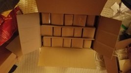
Have drivers will travel...
Well a case of 45 drivers from Madisound showed up this morning (I already had 10 from an earlier order). Not bad considering I placed the order on Wednesday.
Earlier this week I decided to get some actual measurements of these drivers. In my past loudspeaker builds - all which were fairly simple in their design - I just used the published specs. Since this project is going to be much more complex and involved than the earlier ones I figure it's best to get back to the basics.
I updated to the latest version of REW on my laptop and put together the simple rig to measure driver impedance using a USB soundcard. Straight out of the box the first samples had free-space Fs values between 130-134Hz. I figure this may drop closer to the published 125 Hz as the drivers get broken in.
Next step is to build a couple simple test enclosures around 2.3L (the target displacement of my current tower design) and get some initial impressions and play with different stuffing/damping combinations.
Onward and upward.
-b
Attachments
Small update - Christmas eve and right on cue my Onkyo AV receiver gives up the ghost. :-/ Not a lot of love lost here - I've been steadily loosing HDMI ports over the course of the last year. Thank god there were originally like 7 of them for input and 2 for output. I think I was down to 3 functioning inputs and a single output.
What is it about AV receivers these days? It seems like the expected lifespan is about 2.5 years around here. In just a handfullof years I've been through a Sony, a Denon and now the Onkyo.
On the bright side, its replacement arrived today - a Marantz NR1710. And yes, I know they're owned by the same company as Denon and Onkyo.
Kind of a middle of the road 7.2 channel AVR but the the one important feature it does have is pre-amp outputs for the front speakers. This will make it a lot simpler to integrate/equalize the arrays once they are built. I have a big Heathkit amp upstairs which is slated to provide the needed power.
Onward and upward.
-b
What are your plans for cabinet design? I’ve been overthinking pros and cons of various shapes, baffle widths, etc. since I don’t have a good set of corners to place mine in, I’m going to need them a little bit away from the walls, and slightly toed in. Current thoughts are leaning in the direction of using 6” pvc sewer pipe stuffed with fiberglass acoustic panel material I rescued from a demolition job at work. The pipes are cheap, less than $40 ea. The hard part is mounting a baffle to them, since there isn’t a lot of glue that sticks well to PVC. Cutting the pipe lengthwise on the table saw looks kind of sketchy, but I’ve got some ideas, and a couple short lengths left over from another project. If I’m not mistaken, I’ll get about 1.5l per driver internal volume. The originals have less than that, so maybe it’s enough?
I keep running into roadblocks in other parts of my life, but hoping to get rolling on this soon, since I’ve got drivers in hand now too. Looking forward to see what you do also.
I keep running into roadblocks in other parts of my life, but hoping to get rolling on this soon, since I’ve got drivers in hand now too. Looking forward to see what you do also.
If you want to use bass output I'd aim for 2 to 2.2 litre per driver.
Read the warnings from bwaslo about cutting pipe, it can lead to serious harm!
Read the warnings from bwaslo about cutting pipe, it can lead to serious harm!
Oh, I know all the dangers of cutting PVC with woodworking tools! I just looked at the CAD models I’d made, and the original IDS-25 has about 2L volume per driver, and not the smaller amount that I got in my head somehow! Back to the drawing board for me!
Happy New Year everyone!
My current plans for the cabinet mainly focus on keeping it simple (in general) - at least from a construction point of view. It will basically be a skinny, tall box built from a mix of heavily braced plywood and MDF. External depth will be about 12 inches (30cm). If I did my calculations correctly the internal volume will be about 2.2L/driver.
The one fancy thing I am considering is making the sides slightly curved (like a section of a column) by gluing up multiple flat layers of plywood and milling out the profile with a router and a jig. This may also allow me to "dimple" the inside walls a bit, hopefully breaking-up larger resonances. Stay tuned to see if that works. 🙂
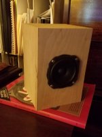
Right now I've just finished gluing up a couple 2.2L enclosures to use for measuring single driver response and evaluating different stuffing options. Got a chance to test out the 3" carbide-tipped hole saw that I bought. I was happy (relieved) to find out the drivers fit perfectly in the resulting cutout with a minimum of play. It will make construction of the front baffle a whole lot faster and easier.
My current plans for the cabinet mainly focus on keeping it simple (in general) - at least from a construction point of view. It will basically be a skinny, tall box built from a mix of heavily braced plywood and MDF. External depth will be about 12 inches (30cm). If I did my calculations correctly the internal volume will be about 2.2L/driver.
The one fancy thing I am considering is making the sides slightly curved (like a section of a column) by gluing up multiple flat layers of plywood and milling out the profile with a router and a jig. This may also allow me to "dimple" the inside walls a bit, hopefully breaking-up larger resonances. Stay tuned to see if that works. 🙂
Right now I've just finished gluing up a couple 2.2L enclosures to use for measuring single driver response and evaluating different stuffing options. Got a chance to test out the 3" carbide-tipped hole saw that I bought. I was happy (relieved) to find out the drivers fit perfectly in the resulting cutout with a minimum of play. It will make construction of the front baffle a whole lot faster and easier.
Last edited:
If you can, do consider using the largest round over you can use on the baffle.
You will have a large amount of drivers, all with the same distance to the edge of the baffle. Like parallel planes this is of more influence in a line of drivers vs a single one.
You will have a large amount of drivers, all with the same distance to the edge of the baffle. Like parallel planes this is of more influence in a line of drivers vs a single one.
Makes sense, thanks!
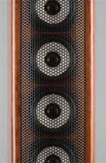
Question - I have seen a couple designs, notably the IDS-25 where the front baffle is not flush but set back and what looks like 3/4" half-round is used on both sides with the grill in between (see attached photo taken from https://ids-25.com/). For this design, what do we see as the tradeoffs between this and a flush front baffle? This would seem to impact off-axis response, but I'm not sure how major an issue that becomes.
Thanks again,
-b
Attachments
Having the front of the baffle edges stick forward a little bit seems mostly to make it easier to mount a grille. I’ve been struggling with how to design a grille into mine without doing that. I might leave it all bare, but I have cats, and sometimes they’re jerks. I’d like keep something between them and the drivers just in case. And I want it to look nice still.
Last edited:
It is something I would avoid at all cost, as that ridge is in common for all drivers and would probably appear in an impulse. However as an array of drivers has all drivers come in at slightly different intervals, such a ridge is not easily noticed in an IR of the array. But that doesn't mean it is a good idea.
If you make a test box with a single driver, you can test that single effect. Basically a smooth transition with flush driver mounting should provide the smoothest response moving from on-axis to the off-axis angles.
The back mounting I use I had seen on another website with on and off axis measurements compared to flush mounted drivers. Basically, I liked what I saw there and moved on to my specific choices. Even though I did have a test box with single driver, it's construction was different.
An array will give you back what you put into it, basically as if on steroids. So any disruption or effect (of a single driver/enclosure) will be enlarged by using that many similar drivers in a row. Be sure to like that single result 😀.
The main reason for me to avoid it: any disruption may point the listener at the speaker location. So it would be worse for imaging. But it also creates bigger differences between on and off axis results (tonality may change).
In my opinion diffraction is best avoided as much as possible for the best results. Just browse trough Mabat's horn tool thread to see the differences between horns that have a smooth roll back mouth vs just a cut off.
So I'd say that grille construction, if it's similar to his prototype, will create an extra obstacle that doesn't have to be there.
Have you seen fluid's elegant solution? Member OPC did something similar quite a while ago. They used a sock that fits over the array to use as grille. He uses felt if I recall correctly to fight diffraction.
It's up to you, many people on this forum don't take diffraction that serious, lot's of rectangular sharp cornered speakers are still being build.
I believe that anything we can do to avoid even the little things builds up to (be able to) create better end results. But that's just a man with an opinion 😉. Part crazy too, look at what I did, tried and build 😀. A self confessed lunatic.
Last edited:
Part crazy too, look at what I did, tried and build . A self confessed lunatic.
You are crazy, but it's our kind of crazy. 😀
Thanks for the thoughts/feedback. I also have two cats also as well as a large russian dog and I am trying to avoid having this considered as a potential scratching post or a chew toy. I've definitely read through the majority of fluid's thread and like the sock, but I think that SAF may require a more traditional grill. I'm pondering the options right now.
To me, the edges there are so small, that maybe their effect is not so noticeable? My plan so far is to put a grille made from a piece of Masonite that sits flush with the front of the speaker, use magnets or Velcro to hold in place. But that necessitates a slightly wider baffle to do that. Heading to the store now to see if I can get bigger pipe than 6”. Worst case for me, I build subwoofers. I did simulations of bass response in speaker box lite, but it doesn’t show the proper rise in low end response, so I’m having a hard time gauging what my ultimate max SPL will be in the bass region with the arrays as they are for a given box size and whether I stress much about having subs take over around 80-100hz.
@anchorman - I've been running grill options through my head and it occurred to me that a pseudo "wrap around" grill using small blocks (say 1" square) of cove molding could anchor to the points just outside the front baffle. the concave curve in the molding could match the curved surface of the column tube.
this approach wan't work for me, but it may for your design.
just a thought.
this approach wan't work for me, but it may for your design.
just a thought.
Last edited:
I would consider a chamfer leading away from the drivers as a good way to avoid diffraction and give some space for the grill to fit.
Here's a graph that shows edge diffraction from different woofer recess options for another speaker I am working on. The step shows what wesayso is saying to say away from. The felt I used to keep the fabric away from the drivers in my array was quite hard and not nearly as absorptive as I thought it would be. Better than wood but not ideal either, I would do it differently if I was to do it again.
"I have also simulated the driver mounted flush, set in 18mm with a 45 deg chamfer, an 18mm roundover and a 13mm vertical step. There is not a huge difference between the chamfer and roundover, most likely due to the limitations on the mesh making the two quite similar. Flush is impractical as the driver has a 13mm step up from the surround but it shows a worst case scenario for this situation. Diffraction off the edge of the basket".
From here 2 way waveguide speaker build ABEC modelling
A little update - playing with the testbox
Finally got around to evaluating a simple test box and playing around with stuffing levels.
The enclosure size is right at 2L. The initial test runs used standard poly-fil pillow stuffing. Not the best, but I had a 2 lbs. bag handy. I plan on testing other "better" materials going forward. Really the purpose of this exercise was to gain more experience with REW and making sure my measurements made basic sense and were repeatable.
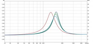
I've attached the impedance graph. The red line is the free-air response. The other curves are from the mounted driver starting with an empty box and increasing levels of stuffing resulting in progressively lower fs and a lower impedance peak. I never did reach the turnaround point where fs starts increasing. I figure the volume is a little too small to find this point easily.
Listening wise, I matched it up against my desk speakers which are a pair of Tang Band W3-881sje in small ported enclosures. No equalization so the W3's had the much better lower end. But the mid and upper range of the TC's did grab my attention a bit. Lyle Mays' piano on "To The End of the World" (off of PMG's "We Live Here") showed a level of detail I did not expect. So initial results seem to be positive. 🙂
-b
Finally got around to evaluating a simple test box and playing around with stuffing levels.
The enclosure size is right at 2L. The initial test runs used standard poly-fil pillow stuffing. Not the best, but I had a 2 lbs. bag handy. I plan on testing other "better" materials going forward. Really the purpose of this exercise was to gain more experience with REW and making sure my measurements made basic sense and were repeatable.
I've attached the impedance graph. The red line is the free-air response. The other curves are from the mounted driver starting with an empty box and increasing levels of stuffing resulting in progressively lower fs and a lower impedance peak. I never did reach the turnaround point where fs starts increasing. I figure the volume is a little too small to find this point easily.
Listening wise, I matched it up against my desk speakers which are a pair of Tang Band W3-881sje in small ported enclosures. No equalization so the W3's had the much better lower end. But the mid and upper range of the TC's did grab my attention a bit. Lyle Mays' piano on "To The End of the World" (off of PMG's "We Live Here") showed a level of detail I did not expect. So initial results seem to be positive. 🙂
-b
Attachments
What worked best for me was the itchy kind of fiberglass. One of few materials that worked trough the entire frequency spectrum I intended to play with these.
Even better results were had with some wool felt on the enclosure walls, and on top of the fiberglass to protect the driver. leaving some room between the back of the driver and that layer of wool felt.

The peak is almost cut in half, while moving it to the left.
Even better results were had with some wool felt on the enclosure walls, and on top of the fiberglass to protect the driver. leaving some room between the back of the driver and that layer of wool felt.
The peak is almost cut in half, while moving it to the left.
- Home
- Loudspeakers
- Full Range
- YAPLA - Yet Another Peerless Line Array